Overload Protection
High temperatures have an adverse effect on insulating materials. It is essential therefore, that electric motors should be provided with protection against overheating. Excess current taken by a motor causes overheating. The protective devices most commonly used, detect this excess current. However excess currents do exist during starting, but as these are not for long periods of time they do not cause overheating. Fuses or MCB’s, cannot be used since the starting current of the motor would cause them to blow / trip. It is therefore desirable for over-current protective devices to have a built in “time lag” to facilitate such starting currents. The over- current protective device referred to above is called an overload relay. Fuses or MCB’s are used in conjunction with overload relays to provide protection against short circuits, earth faults or faults in the main wiring.
Overload Relay
There are two types of overload device in use;
· The thermal overload relay
· The magnetic overload relay
The thermal overload relay is the more popular type and is the only one covered in Phase 2.
Thermal Overload Relay
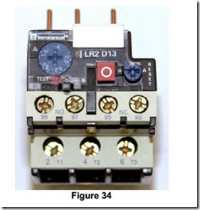
Figure 34 shows a popular type of thermal overload relay. It is suitable for the protection of a motor with a Full Load Current of any value from 1.6 Amps to 2.5 Amps. This value can be set using the current range adjustment. It also features a stop button, a hand / auto – reset button and a test button. It has one N/O and one N/C auxiliary contact. When installed and properly adjusted it may be sealed to prevent / monitor any unauthorised interference with the settings.
The three pins protruding from the top are connected directly into the outgoing terminals of a contactor. Two of these pins are adjustable so that they can be matched up to a number of different size contactors. See underneath pins for this information.
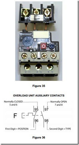
The overload relay may also be installed using a terminal block for separate mounting. Again the pins are adjusted to suit the terminal block. See Figure 35.
Operation of Thermal Overload Relay
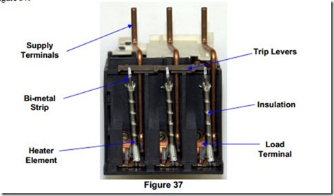
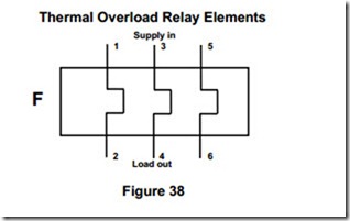
A thermal overload relay works on the principle that, current flowing through a conductor produces heat. If the current is doubled in value the amount of heat produced will be quadrupled. The current taken by a three phase motor is passed through a set of three small heater elements. One heater is wrapped around each of the three bi-metal strips as shown in Figure 37.
The operation of the thermal overload relay is as follows:
Under normal conditions the heat produced by the heater elements is just balanced by the heat lost from them to the surroundings and consequently there is no effect on the bi-metal strips. When an overload current flows, more heat will be produced by the heater elements, resulting in further heating of the bi-metal strips, thus causing them to bend more. This bending of the bi- metal strips changes the position of the trip lever, which causes the auxiliary contacts to change over.
The N/C contact opens and is used to disconnect supply from the contactor coil, thereby disconnecting the supply from the motor. The N/O contact closes and is generally used to supply a signal lamp to indicate that the overload relay has tripped.


