VALVE ACTION
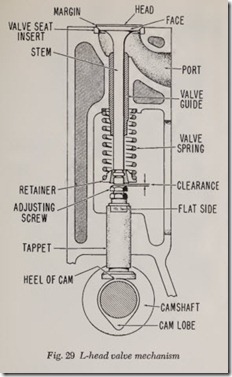
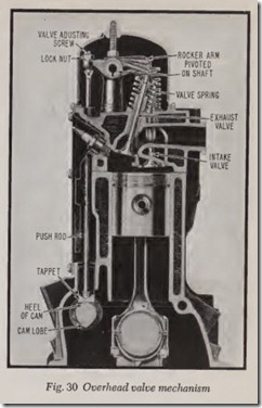
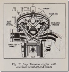
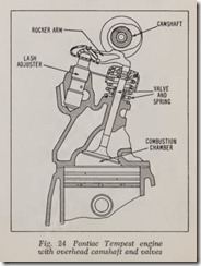
As explained previously, there are two common types of poppet valve designs in use, namely L heads and overheads. Fig. 29 shows an L-head with a mushroom tappet and Fig. 30 shows the overhead design with barrel tappets and long push rods. A variation of the overhead design is the overhead camshaft which does not use push rods or valve lifters, Figs. 23 and 24.
The valve is opened by a cam on the camshaft and closed by the valve spring.
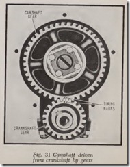
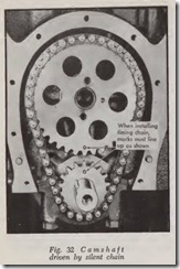
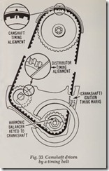
The camshaft is rotated by the crankshaft by gears, Fig. 31, a link type chain, Fig. 32, or by a belt, Fig. 33. In either case the camshaft rotates at half the speed of the crankshaft. This 2 to 1speed ratio between crankshaft and camsh aft is obvi ously necessary because the crankshaf t produces two piston strokes per crankshaft revolution. It should be remembered that four piston strokes, two down and two up, are required to complete the combustion cycle. Therefore, each valve must open and close once for each two revolutions of the crankshaft. This means that the camshaft must run at half the speed of the crankshaft.
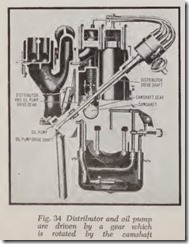
The camshaft drives the oil pump, distributor and fuel pump. In most cases the distributor and oil pump are driven by the same shaft, Fig. 34. The fuel pump is driven by an eccentric (or cam) on the camshaft.
The power of the engine depends on the free flow of gases into the cylinders and out through the exh aust system. The greater the weight of air pumped into the cylind ers and the less the ex haust back pressure the greater the power devel oped. Power increases with weight of air. Free flow of mixture into the cylind er depends on the size of the opening the intake valve provides-the larger its diameter and the higher its lift, the larger the opening. The same is true of the ex haust valve.
However, there is a practical limit to valve diameters and lift. The diameter is limited be cause the cylinders are crowded togeth er so that the engine won’t be too long or heavy. Space and wear considerations also limit the lift. Therefore the lift is usually about J ” and the valve diame ter is, for a typical 240 cubic inch engine, B to 1% inches. Sometimes both valves are made the same diameter but on most engines the diameter of the intake is made larger than the exhaust valve because a large intake valve is more important than a large exhaust valve from a power stand point. Therefore, on the typical engine just men tioned the intake valve is likely to be 1% inches in diameter and the exhaust valve 1 inches di ameter.
Valve seat angle is usually 45 degrees although on some engines it is 30 degrees (or a combina tion of both angles). The 30-degree seat gives a larger valve opening for a given lift, and therefore
more breathing capacity and more power. On the other hand the 45-degree design gives a better wedging and centering action between valve face and seat and therefore provides a more leak-proof valve closing.
VALVE TAPPETS OR LIFTERS
It is not desirable to allow the cam to act directly on the lower end of the valve stem and therefore a lifter (tappet) is inserted between cam and valve stem. The slim valve stem is in capable of taking the side thrust of the cam without undue wear of stem and stem guide. Also the area of the bottom of the stem is too small to properly resist the wear of the cam which rubs against it. Finally, a means of adjustment is re quired between cam and valve stem on L-head engines and this adjustment is most conveniently located in the top end of the tappet (unless hydraulic lifters are used).
The adjustment is required to provide slight clearance between tappet and stem so that the valve can close tightly even when the stem is very hot and therefore fully expanded or lengthened. Clearance for a warm engine may range from ap proximately .006″ to .022″ or more, depending on the engine design.
On most L-head engines the adjustment consists of a screw and lock nut in the top of the tappet, Fig. 29. In this case there are opposite Bat sides on the lifter so that it can be held against rotation while the screw is adjusted and the lock nut is tightened. Three wrenches are required for this job.
On some L-h ead engines, a self-locking screw is used thus eliminating the lock nut. In this case the tappet is held with one wrench until the desired clearance is obtained.
On overhead valve engines , the adjustment is on the rocker arm, Fig. 30. The adjustment is made by turning the screw after loosening the lock nut.
CAMS
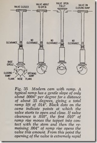
The cam which raises th e valve tappet is a very carefully designed part, Fig. 35, which is accu rately finished. Part of it is circular. This portion is called the base circle or heel. The pointed part of th e cam which opens th e valve is called the lobe while the tip of th e cam is of ten referred to as the nose. The valve is f ully open when the nose is in contact with the center of the tappe t.
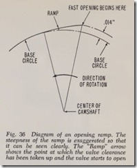
Modern cams, Fig. 35, are divided into five part s: ( 1) base circle, ( 2) openin g ramp, ( 3) opening flank, ( 4) closing flank, ( 5) closing ramp. An opening ramp is diagrammed in Fig. 36. The closing ramp is similar.
The speed at which the flank of a cam opens a valve is very rapid. To soften the blow the cam is provided with an opening ramp . Without a ramp the flank of the cam starts to bump the valve open at an almost incredible rate. In the case of an average engine running 4,000 rpm, the flank of the cam opens the valve in approximately 1/100 sec ond. Closing of the valve requires about the same amount of time. Compared with the flank of the cam, th e opening ramp has a very gentle slope which raises the lifter only about .014″ while the camshaft rotates about one-tenth of a revolution.
The rise of the ramp is much less with hydraulic valve tappets because valve clearance is zero. This comparativ ely slow motion eases the lifter gently up against th e valve stem and then eases the valve open. After this happens, the flank of the cam starts pushing th e lifter at an extremely rapid rate. Obviously the ramp prevents undue wear of the valve mechanism. However, the principal purpose of th e ramps is to reduce valve noise.
The main purpose of the closing ramp is to reduce th e speed at which th e valve hits the seat, th ereby r educing valve noise as well as wear of valve face and seat caused by the hammering action. Cocking of the valve stem in its guide causes the valve head to hammer the seat at one point , tending to increase noise and wear. The closing ramp largely nullifies these troubles.
LOCATING VALVES
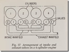
The arrangement of the intake and exhaust valves varies on different engines. On all engines the valve arrangement ean be determined by an inspeetion of the branehes of the intake and ex haust manifolds. It should be obvious that it is neeessary to be able to distinguish b etween intake and exhaust valves in eonneetion with various engine repair operations sueh as adjusting valve operating elearanees.
Fig. 37 illustrates the arrangem ent of intake and exhaust valves on a typieal four-eylinder engine and on both banks of some popular V8’s as well.
E-I-I-E-E-I-I-E
Among the arrangements used on six-eylinder engines, there is the one used on Chevrolet, Dodge and Plymouth whieh is:
E-I-I-E-E-I-I-E-E-I-I-E
The valve arrangement on some Ford Co. and late Rambler six-eylinder engines is:
E-I-I-E-I-E-E-I-E-I-I-E
Late Ford six-eylinder arrangement is:
E-I-E-I-E-I-E-I-E-I-E-I
Early Rambler six-eylinder engines use:
I-E-E-I-I-E-E-I-I-E-E-I
VALVE SPRINGS
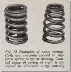
Valve springs are made of round steel \vire about ineh in diameter. The wire is wound as shown in Fig. 38. The spring is ground flat on both ends so that it seats squarely. On a typieal engine, the free or uneompr essed length of the spring is 2-3/32″. Wh en the spring is installed and the valve is elosed, the length is H” and the spring pressure is 40 pounds for a typieal L-head engine. When the valve is open, the spring length is 1-7/ 16″ and the pressure is 83 pounds. The open valve obviously has been lifted 5/16″ ( H minus 1-7/16).
On a comparable overhead valve engine, the free length of the spring is 2-3/32″ as before. The installed length of the spring when the valve is closed is 1-11/16″ and the pressure exerted is 53 pounds. When the valve is fully open the spring length is 1-11/32″ and the pressure is 146 pounds. The lift of this valve is 11/32″.
After many miles of use, valve springs may weaken, in which case valves and tappets may not keep in contact with their cams. This means that ( 1) a valve may bounce open farther than the lift it was designed for and ( 2) it may not close promptly. In oth(_(r words, weak springs may com pletely upset valve action and thereby reduce the power production of the engine. Therefore it is important to check the strength of valve springs whenever a valve grinding job is done or when the valves are removed for any other reason.
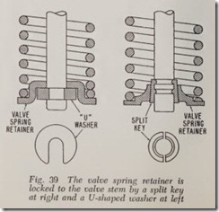
In an L-head engine, the upper end of the valve spring, Fig. 29, pr esses against the cylinder block while the lower end of the spring pushes against the valve spring retainer which is attached to the lower end of the valve spring. In an overhead valve engine, Fig. 30, the lower end of th e spring presses against the cylinder head while the upper end presses against the spring retainer attached to the valve stem. On most engines the retainer is held in place by a tapered split key although a U shaped washer will be found on some of the older cars, Fig. 39.
A valve spring may break for two reasons: it may be overstressed or it may have a tiny crack in its surface. Under use, the crack is gradually enlarged until the spring breaks . This is called fatigue.
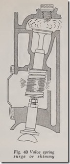
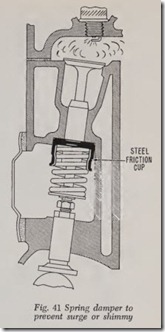
Overstressing of a spring is usually caused by an up-and-down vibration in the spring, Fig. 40, which occurs at certain engine speeds. This phe nomenon is called spring surge or shimmy. There are various ways of preventing or suppr essing spring shimmy. One method is to provi de a fric tional vibration damper, Fig. 41, which pr events the spring from going into a dance. Another method is to use a spring which is so stiff that it will not vibrate at engine operating speeds, say up to 4,000 rpm. A third method is to use a spring with unevenly spaced coils, Fig. 38. Each coil wants to vibrate at a different engine speed with the result that the spring as a whole is unable to vibrate at any engine speed. A fourth cure is to employ two concentric springs. The vibration rates of the two springs are different at all engine speeds. Therefore if one spring tries to get into a dance at some certain engine speed, its act is dis couraged by the other spring.
Suppression or elimination of valve spring surge is most important for two reasons: ( 1), The vi brating spring is overstressed and therefore may break; ( 2) spring shimmy interferes with correct valve action in about the same way that a weak spring does. In other words, an upsurge at the right instant may permit the valve to open too far (while the lifter bounces away from the cam) or if an upsurge should occur while the valve is closing, the closing may be delayed with resulting loss of power. The maximum speed of some en gines is limited by valve spring surge. In other words, at some certain high speed the springs go into a dance which completely upsets valve action and then power production is sharply reduced.
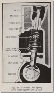
On some Studebaker engines, a U-shaped flat spring, Fig. 42, is placed between the valve spring retainer and the valve tappet. Its purpose is to hold the tappet against the cam when the valve is just closed and thus avoid the possibility of a slight noise due to the lifter clattering on the heel of the cam.
CYLINDER BORE DISTORTION
If someone were able to make an ideal engine it would consist of perfectly round and straight cyl inder bores and perfectly round and straight pis tons which slide up and down in these bores. Un fortunately this ideal can only be approxima tely realized.
When the cylinder block is manufactured the bores are round and straight within much less than a thousandth of an inch. But bolting the cylinder head in place distorts the straightness of the bore and may even pull it a little out of round . To keep this distortion to a minimum, car manu facturers specify just how tight the cylinder head bolts should be. Bolts too tight will cause undue distortion. On the other hand, if bolts are too loose, leakage will occur at the gasket. In order to tighten the bolts just the proper amount it is desirable to use a torque wrench. This wrench indicates the pull in pounds that are applied to the wrench. Each car maker issues instructions as to how much the pull should be.
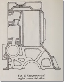
The cylinder bores are machined at room temperature but in an actual engine the temperature is a few hundred degrees higher. Metals expand when they are heated. If an engine had bores which were not attached to the block, no appre ciable distortion would occur when they were heated but unfortunately the bores are usually an integral part of the cylinder block which is an unsymmetrical piece of metal which includes water jackets, valve chambers and upper half of crank case, Fig. 43. These parts expand in different ways with the result that the bores are distorted when heated.
PISTONS
The piston likewise is straight when it is manu factured (at room temperature). Whether it is made round or slightly oval depends on its design . An oval piston when cold may be p ractically round when hot.
Neither the cylinder bore n.or the piston skirt is perfectly stiff which means that both th e gas pressures and the inertia pressures acting on the piston slightly distort the wearing surfaces of both bore and piston skirt. ·
A small amount of clearance between piston and cylinder bore must be allowed for the oil :S.lm which must coat both surfaces in order to sup press wear. Some additional clearance between piston and cylinder bore is required when the engine is cold because the piston expands mor e rapidly than the cylinder bore as the engine warms up because the piston is hotter than the bore when the engine is operating.
Although cylinder bore distortion and piston skirt distortion only amount to a few thousandths of an inch, the result is importa t w n it .:i , remembered that a piston in a typical en-gine;”·
operating at a speed of 4,000 rpm travels at an ‘ average speed of half a mile per minute.
Aluminum Pistons
Ordinary aluminum alloy pistons expand at about twice the rate of the cast iron bore. There fore, special provi ions are made in aluminum alloy piston designs to control piston expansion. There is, however, a special silicon-aluminum al loy with a low expansion rate used in some pistons.
All other aluminum alloy pistons have special design features so that the clearance when cold is not enough to permit objectionable slap and yet when the piston becomes hot there is still enough clearance so there is no danger of the piston stick ing in the bore.
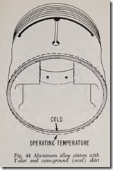
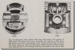
Numerous types of aluminum alloy pistons have been introduced, all designed to take care of the expansion problem in one way or another. How ever, it would serve no useful purpose to describe all the various designs here. Instead, the two types in common use will be discussed, namely: The T slot piston with “cam-ground” skirt, Fig. 44 and the invar strut piston, Fig. 45. lnvar is a steel alloy containing about 36 per cent of nickel. The expan sion rate of invar is practically zero. Both pistons are slotted horizontally between the head and skirt in order to provide a heat dam to reduce the amount of heat flowing from piston head to skirt and thereby reduce skirt expansion.
Returning to the T-slot design, Fig. 44, it will be seen that the T-slot is formed by a horizontal slot between the piston head and piston skirt which connects with a nearly vertical slot in the piston skirt. The opposite side of the piston has a hori zontal slot but no vertical slot. The horizontal slots act as heat dams to prevent undue heat from flowing from piston head to skirt. The nearly vertical slot provides enough flexibility in the skirt to discourage the possibility of the skirt sticking fast in the bore. The skirt is relieved (under cut) in the region of the piston pin hole so that any undue expansion in this region will not cause the piston to seize in the bore. Too much flexibility in the skirt, however, is undesirable and it is for this reason that the slot is not continued all the way down through the lower edge of the skirt. The slot length shown gives the desired flexibility. Too much flexibility would permit rocking of the piston in the bore and would in time slightly round off the outer surfaces of the piston rings and thus render them less effective against leak age of both gas pressure and oil.
If the slot in the skirt were vertical it would gradually make a ridge in the bore. To avoid this the slot is slightly diagonal.
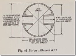
The skirt of the piston is ground slightly ellipti cal, Fig. 46. In a typical case , the piston diam eter is .006″ less when measured across the piston pin holes than when measur ed across the “large” diameter. The elliptical piston is called a cam ground piston because the grinding wheel position is controlled by an elliptical cam. Note that with a cam-ground piston the front and rear surfaces may not contact the bore at all. The terms front and rear mean front and rear with respect to the engine block.
The skirt of the cam-ground T-slotted piston may be fitted to the cylinder bore with close clearance in a cold engine. When the engine be comes warm and the piston expands, the skirt (because of the T-slot) tends to shape itself to the cylinder bore without any danger of the piston sticking in the bore.
Piston Side Thrust
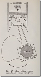
When a piston moves down on its power stroke, the angularity of the connecting rod causes it to be pressed against the cylinder bore surface which is opposite the crankpin, Fig. 47. This side of the piston is often called the major pressure side or major thrust side while the other side is called the minor pressure side. Many car makers recommend that the T-slot be located on the camshaft side, thus enabling the stiffer major pressure side of the piston to resist the side thrust caused by combus tion pressure.
However, at high speed the inertia forces acting on the piston are greater than those caused by gas pressure and they act alternately on both sides of the piston as it moves up and down. As the piston rushes down it presses against one side of the bore and as it rushes upward it presses against the other. Therefore both sides of the piston are sub jected to the same inertia side thrusts during each revolution of thP engine. Gas pressures and inertia pressures should be considered separately.
At low speed, when inertia forces are low, gas pressure is high when the throttle is open. There fore, some engine manufacturers place the T-slot on the major pressure side because the resilient T slotted skirt cushions tendency to piston slap.
To sum up, the T-slotted aluminum cam ground piston is able to work successfully in a cast iron cylinder bore for three reasons, namely: ( 1) Flex ible skirt obtained by (nearly) vertical slot. ( 2) Cam grinding (oval) which enables the piston to fit itself to the bore automatically. ( 3) Heat dam which prevents most of the heat on the piston head from reaching the skirt.
The skirt is flexible circumferent ially. Longi tudinally the skirt is rigid enough so that it does not wobble in the bore; also the skirt has sufficient lengthwise rigidity so the outer faces of the rings move straight up and down in the bore. By con trast, a skirt that is flexible lengthwise would cause the outer faces of the rings to wear round and thus reduce their effectiveness.
