Another type of rotor current control uses liquid as its resistance. Three plates (connected to the slip ring leads) are lowered into a liquid. Current flow increases as the plates are lowered. The current control is much smoother than one with resistors and contacts.
Reversing the Wound Rotor Motor
Interchanging any two stator leads reverses the wound rotor motor. Interchanging the rotor leads won’t reverse this motor, because the stator poles determine the polarity of the rotor poles.
The wound rotor motor should not be plugged (reversed) while running. Plugging transforms a very high voltage into the rotor winding. Voltage produced (by plugging) in the wound rotor winding is too high for the circuit’s insulation.
The highest voltage will be at the end of the phases (leads). (The rotor circuit’s weakest insulation is between the exposed metal of the slip rings and the shaft.) If one slip ring is grounded to the shaft, the insulation thickness between the rings is cut in half. Arcing will occur between one or both of the other two slip rings and the shaft. Brush dust contamination (in the slip ring area) increases the chances of an arc forming.
Plugging has resulted in rotor winding leads being blown off the slip rings. Voltage dramatically increases in the rotor winding, and has caused a flashover between the slip rings.
Wound Rotor Motor Used as a Variable-Voltage Transformer
A wound rotor can be used as a three-phase variable-voltage source. A geared device controls the movement of the motor’s shaft. The stator winding acts as the primary of the transformer, and the rotor winding is the secondary.
The slip rings aren’t used.
When the rotor is moved, the voltage transformed into the rotor poles varies as their alignment with the stator poles changes. Total pole-to-pole alignment produces full voltage output. When the rotor poles are moved 90 electrical degrees out of alignment (one-half pole), the voltage output is at its lowest value.
The device that controls the rotor’s movement has to be strong enough to withstand the motor’s full torque. Torque develops when amperes flow in the rotor windings. The rotor windings are usually redesigned and rewound to produce the desired voltage.
Wound Rotor Motor Used as a Hertz Changer
Before the development of electronic hertz controls, a specially modified wound rotor motor was used to produce 120-Hz power. The power was achieved by energizing the wound rotor motor’s stator and driving its shaft against its rotation with another motor. The power was tapped off the slip rings of the wound rotor motor. The quality of power produced by this method is better than today’s electronically produced 120-Hz power.
The Brushless DC Motor
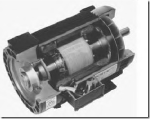
The brushless DC motor is a type of three-phase synchronous motor (Fig. 5.51) with permanent magnets on its rotor. (Most synchronous motors have coils on their rotors, powered by DC.)
Like the synchronous motor, the brushless DC motor has absolute speed regulation. The speed control is exact ( ± 0). Unlike the synchronous motor, this motor doesn’t shut down if it’s overloaded. When there is an overload, the controller will automatically adjust the hertz to a different RPM.
The power range of brushless DC motors is from 1 /4 to 400 horsepower. They have NEMA standard frame sizes and enclosures, and the controllers operate on either 50- or 60-Hz power sources.
The brushless DC motor control can include dynamic (regenerative) braking to slow a momentum load. It has full-load torque at zero speed,
for use as a brake or as a servomotor. Its acceleration and deceleration capabilities are typically 0.05 to 90 seconds, and they are separately adjustable in the controller. It has electronically controlled plugging capability (reversing) at any speed. The motor’s current and voltage are electronically limited when the motor is plugged. This decreases highampere stress that plugging typically causes in other types of motors.
The brushless DC motor can withstand a 150 percent overload for 1 minute. It’s protected with instantaneous trip action when the current exceeds 250 percent.
It has nearly unity power factor at all speeds and loads. Magnetizing amperes are limited to the stator. The rotor doesn’t require any magnetizing current since the rotor’s magnetic field is supplied by a permanent magnet. (The squirrel cage rotor requires continuous magnetizing.)
