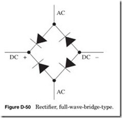
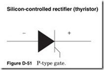
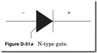
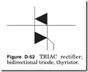
Rectifier, general
Arrow points in the direction of the current flow as indicated by a DC ammeter. Electron flow is in the opposite direction.
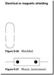
A shunt (Fig. D-57) is typically used on an ammeter or a current trans- former. A shunt should be installed on any secondary of a current trans- former when it is not connected to a load.
Related posts:
Troubleshooting AC motors and starters:Motor enclosures
summary of Transformers
Tutorial Problems on Transformer
Fixed Appliance and Socket Circuits:Special Outlets
Field effect transistors (Fets):TESTING FETs
Testing Motors in Place
VARIABLE-SPEED DRIVES:INVERTERS
Power Supply Design:Series Regulator Layouts
Troubleshooting control circuits:Troubleshooting examples
Electrohydraulic Servo Motors:A Simple Mechanically Controlled Servo System
Speed control of d.c. Motors:Merits and Demerits of Rheostatic Control Method
How Engines Work part5
Braking:Mechanical Brakes
Switch principles:Contact resistance

![Figure-D-54-Resistor-adjustable-rheo[2] Figure-D-54-Resistor-adjustable-rheo[2]](http://machineryequipmentonline.com/electric-equipment/wp-content/uploads/2020/06/Figure-D-54-Resistor-adjustable-rheo2_thumb.jpg)
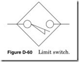
![Figure-D-61-When-the-outputs-and-inp[1] Figure-D-61-When-the-outputs-and-inp[1]](http://machineryequipmentonline.com/electric-equipment/wp-content/uploads/2020/06/Figure-D-61-When-the-outputs-and-inp1_thumb.jpg)
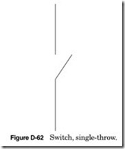
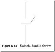

![Figure-D-65-Foot-switch-closed-by-fo[1] Figure-D-65-Foot-switch-closed-by-fo[1]](http://machineryequipmentonline.com/electric-equipment/wp-content/uploads/2020/06/Figure-D-65-Foot-switch-closed-by-fo1_thumb.jpg)


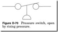
![Figure-D-71-Pressure-switch-closed-b[2] Figure-D-71-Pressure-switch-closed-b[2]](http://machineryequipmentonline.com/electric-equipment/wp-content/uploads/2020/06/Figure-D-71-Pressure-switch-closed-b2_thumb.jpg)
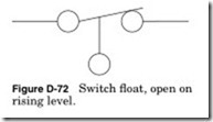
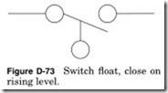
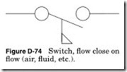
![Figure-D-75-Switch-fl-ow-open-on-fl-[1] Figure-D-75-Switch-fl-ow-open-on-fl-[1]](http://machineryequipmentonline.com/electric-equipment/wp-content/uploads/2020/06/Figure-D-75-Switch-fl-ow-open-on-fl-1_thumb.jpg)
