How a Carburetor Works
In order for a carburetor to deliver fuel to an automobile engine under all operating conditions it must have the following features:
1. A float system which provides a means of stor ing fuel to be used as needed.
2. A throttle valve to control the speed of the en gine.
3. An idle and low speed system for engine operation while standing still and for speeds up to about 20 miles per hour.
4. A part throttle system for operation at cruising speeds.
5. A power system for operating at high speeds.
6. An accelerating pump system to furnish an extra charge of fuel for quick bursts of speed as in passing a car.
7. A choke system to supply a richer air-fuel mixture for starting a cold engine.
FLOAT SYSTEM
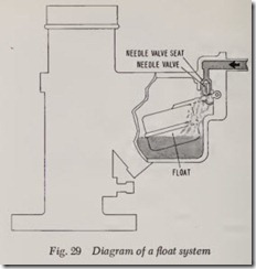
Fig. 29. The fuel pump delivers gasoline to the float bowl. As the fuel enters the float bowl through the open needle valve, it raises the float until the needle valve, which is attached to the float, closes in its seat, thus preventing any more fuel from entering the float bowl.
As the fuel is used up by the engine, the float gradually drops, the needle valve opens, allowing more fuel to be pumped into the float bowl by the fuel pump.
THROTTLE VALVE
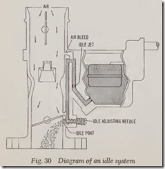
The throttle valve controls the amount of air fuel mixture passing through the carburetor, theretsy controlling the speed of the engine. The throttle valve is a round, flat metal plate attached to a throttle shaft. The assembled plate and shaft is positioned in the carburetor, Fig. 30. When closed it prevents air from passing through the carburetor; when open it permits air to flow through. The quantity of air flowing through the carburetor when the throttle valve is open is de termined by the degree of opening. This is con trolled by the accelerator pedal which is linked to the throttle shaft.
IDLE AND LOW-SPEED SYSTEM
Let’s assume that you are waiting for a red traffic light to change to green. The engine is warm and running at idle speed and your foot is on the brake pedal. Under these conditions the throttle valve is closed, Fig. 30.
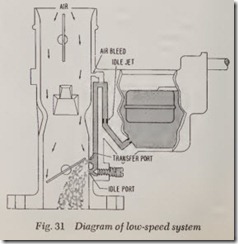
Since the throttle valve is closed, we have to provide a means of admitting air-fuel mixture under the throttle valve, otherwise the engine would not run. To accomplish this, two openings are provided in the air passage, one below the throttle valve (idle port) and the other ahove it ( tr ansfer port). These two openings are con nected by a passage, the function of which is to allow air to by-pass the closed throttle valve. A second passage is also provided, one end of which communicates with the fuel in the float bowl and the other end to the top (air) opening, Fig. 30.
Now, with the engine idling, the engine pistons are creating a suction (vacuum or low air pres sure), but with the throttle valve closed, the main air passage through the carburetor is blocked so that the low pressure area is under the closed throttle valve. However, since the lower opening (idle port) is under th e throttle valve, air natu rally rushes down the vertical passage. At the same time the low pressure in the vertical passage also lowers the pressur e in the passage which communicates with the float bowl. As a result fuel (which is under ahnospheric pressure) is forced out of the float bowl and through the passage where it is mixed with the air stream rushing down the vertical passage to the idle port opening, from whence it is delivered to the engine. As shown, an adjusting needle at the idle port can be turned to provide a leaner or richer air-fuel mixture.
For low speed operation ( 15 to 20 mph) the throttle valve is opened a little, gradually exposing the transfer port, causing a discharge of air-fuel mixture from this port as well as the idle port, Fig. 31.
The quantity of gasoline fed to the idle and low speed system is controlled by the idle or low speed jet, Fig. 31. A jet is a fitting with a hole drilled in it to a precise dimension so only a pre determined quantity of fuel can pass through it.
PART THROTTLE SYSTEM
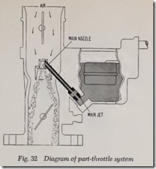
When the traffic light turns green you step on the accelerator pedal lightly. This opens the throttle valve, which no longer blocks the passage of air through the carburetor. Thus, the low pres sure at the idle passage no longer exists. In conse quence, the idle and low speed system stops functioning and the main metering or part throttle system automatically comes into operation, Fig. 32.
Air now rushes down through the carburetor and past the main nozzle sucking a quantity of fuel out of the nozzle to mix with the air stream. The resultant air-fuel mixture is delivered to the engine.
The amount of gasoline fed to the main nozzle is controlled by the size of the hole drilled in the main jet.
The part throttle system operates only at cruis ing speeds depending on carburetor design.
POWER SYSTEM
It should be obvious that it requires more fuel to run a car at 80 miles per hour than at 50. For this purpose it is necessary to supply additional fuel for the richer “power” mixtures during wide open throttle and high speed operation. Two methods are used to supply this richer mixture, the power valve and the metering rod.
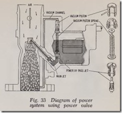
Power Valve: The power valve provides addi tional fuel for high speed operation by permitting fuel flow through an auxiliary power jet, Fig. 33. Normally controlled by a vacuum-operated piston or diaphragm, the power valve is held closed by intake manifold vacuum until the throttle valve is opened and the manifold vacuum falls below 4 to 6 inches of mercury. A spring then forces the valve open, permitting fuel to flow through the power jet and to join that discharged by th e main jet.
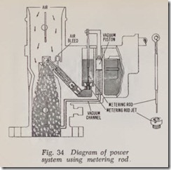
Metering Rod: In this design, Fig. 34, all fuel is metered through the main jet (metering rod jet) during both part throttle and full throttle opera tion. Like most other jets, the metering rod jet is just a fitting with a precisely drilled hole through which fuel can pass from the float bowl to the main nozzle. The metering rod fits into this jet, which is a metal rod with several steps on it, each successive step somewhat larger in diameter than the preceding one. The metering rod is raised out of its jet and lowered into it in direct relation to the pressure applied to the accelerator pedal.
Like the power valve discussed above, the metering rod is normally controlled by a vacuum operated piston. During part throttle operation, the larger section of the rod is in the jet, restrict ing the flow of fuel. As the throttle valve is openedwider by depressing the accelerator pedal, the metering rod is lifted correspondingly out of the jet, so that a smaller diameter section of the rod is now within J:he jet and more gasoline can enter the main nozzle. When the accelerator is de pressed to its limit, the thinnest diameter section of the metering rod permits the maximum quan tity of fuel to flow into the main nozzle.
ACCELERATING SYSTEM
Let’s say you are driving at 35 miles per hour and want to pass a car in a hurry. Of course, you step on the accelerator pedal and thus open the throttle valve wide. By doing this, one would think that this should increase the amount of air flowing through the carburetor and with it the amount of fuel sucked out of the float bowl. Actually, however, the air responds to this sudden demand quickly, but gasoline, being much heavier than air, lags behind, so that the result would be just a lot of air but not enough fuel to push the engine into high speed. To overcome this defi ciency, we use the accelerating system.
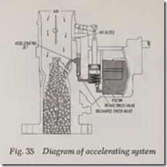
As shown in Fig. 35, a typical accelerating pump system consists of a piston linked to the throttle, two check valves, an air bleed and a jet. When the throttle is closed, the piston draws fuel into its cylinder through the intake check valve. As the throttle is opened suddenly, the piston forces fuel through the discharge check valve and the accelerating jet into the carburetor air stream, just enough to mix with the air until fuel starts coming out of the main nozzle. As a result, there is no flat spot in the operation of the engine when fast acceleration is desired, and the acceleration is smooth and fast.
Since a low pressure (vacuum) occurs at the accelerating jet during normal operation, an air bleed is incorporated to counteract this vacuum, thereby preventing syphoning of fuel when the accelerating pump is not operating. This is accom plished by a higher air pressure being applied to the air bleed.
CHOKE SYSTEM
When a cold engine is being started it requires a richer air-fuel mixture, that is, one that contains a higher proportion of gasoline than when the engine is warm. To accomplish this, an additional valve is placed in the air inlet of the carburetor (air horn) above the main nozzle so that when this valve is closed, it greatly reduces the normal air flow in the air horn. This results in extreme unbalance of air pressures. In the air horn, the vacuum produced by the pistons of the engine reduce the pressure to about 5 pounds per square inch, while a pressure of nearly 15 pounds (at sea level) acts upon the gasoline in the float bowl. This difference in pressure forces a lot of gasoline from the float bowl into the air passage and into the cylinders, producing the rich mixture neces sary to start a cold engine. As soon as the engine is warm, the choke valve must be opened in order to restore the normal air-fuel ratio.
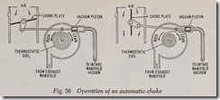
Although on some cars the choke is operated manually by the driver, most modern carburetors are equipped with a built-in automatic choke con trol which is a combination of a thermostatic bimetal coil spring and a vacuum-operated piston, Fig. 36. Both the spring and piston are linked to the choke valve.
During cold starting the coil spring holds the choke valve closed. As soon as the engine starts, intake manifold vacuum acting on the piston op poses the spring action, tending to open the choke. As the engine warms up, heat drawn from the exhaust manifold through a tube causes the thermostatic spring to lose its tension, thereby permitting the choke valve to fully open.
VENTURI ACTION
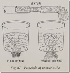
If a constriction (venturi) is placed in a pipe and water is forced through the pipe, the water in the constriction will flow faster than the water in other parts of the pipe. This principal can easily be demonstrated by allowing water to flow from a garden hose with a tapered nozzle and without a nozzle. The taper in the nozzle forms the restric tion and since its diameter is smaller than the diameter of the hose, the water will flow faster out of the nozzle than it will if no nozzle is attached to the hose.
Similarly, if two containers filled with water are placed side by side, one with a one inch plain opening and the other with a one inch venturi or bell-mouth opening, Fig. 37, the water will flow out of the venturi opening at a faster rate than out of the plain opening.
This same accelerating action takes place as air flows through the venturi of a carburetor .
A venturi tube in a carburetor will develop increased air flow and a higher vacuum within the venturi throat. A problem in carburetion is to secure the correct amount of suction around th e needle valve at slow engine speeds and still allow enough air to enter at high engine speeds to maintain the desired ratio of air and fuel. The venturi tube lends itself to these extremes by increasing the vacuum at low speeds without re stricting the flow of air at high speeds.
As the piston within the engine cylinder moves downward on the intake stroke, a suction is cre ated around the fuel nozzle in the narrowest part of the venturi and air enters and picks up the gasoline as it passes. After passing the venturi, the partially atomized air and gasoline enters a mixing chamber below the venturi and completes atomi zation. A partial vacuum exists in the mixing chamber and just as water boils more readily in a vacuum than it does under normal air pressu re, so gasoline tends to vaporize more readily in this partial vacuum.
Venturi size must of necessity be a compromise for both h igh and low speed operation. Because the m aximum power an engine can develop is limited by the amount. of air it can breathe in, the venturi size should offer minimum resistance to the larger volume of air flowing at high engine speed . On the other hand, a small venturi is desirable at low engine speeds to provide suffi cient air velocity for controllable fuel metering and good fuel atomization.
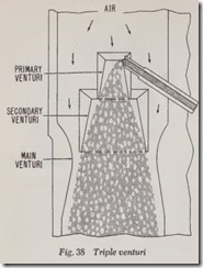
The modern approach to this problem is the use of two or more venturis arranged in series, Fig. 38. Commonly used in modern carburetors, the mul tiple venturi design serves two purposes: First, the added venturis build up air velocity in the smaller primary venturi, thereby increasing the f orce available at the main nozzle for drawing and atomizing fuel. Second, air by-passing the primary venturi forms an air cushion around the rich mix ture discharged by the venturi, tending to im prove mixture distribution by preventing fuel from contacting the carburetor walls.
BALANCED CARBURETOR
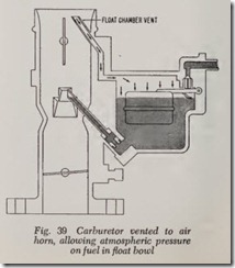
The modern carburetor not only must incorpo rate all the features discussed previously but it must eliminate outside affects on air-fuel ratios such as a dirty air cleaner.Regardless of the excellence of design, air cleaners off er some resistance to the flow of air throu gh their filtering elements and passages. Moreover, the air-fu el mixture varies with air cleaner cleanliness, increas ing as the filter be comes clogged. This variable effect is essentially overcome in modern carburetors by venting the fuel bowl to the carburetor air horn above the choke valve, as shown in Fig. 39. By this means, the only pr essur e difference causing the fuel to How during cruising and high speed operation is that created by air velocity through the venturi. This construct ion is known as a balanced carbu retor.
AIR BLEED PRINCIPLES
Various m eans of m ixture compensation have been employed to correct the enrichening effect of the main j et when air How increases. Most modern automobil e carburetors, however, employ the “air bl eed” principl e to insure uniform air-fuel mixture ratio during part throttle operation. Before de scribing its operation, the principles of the air bl eed must be und erstood.
In a plain tube elementary carburetor, the cor rect fuel supply is maintained by the main jet. A venturi is placed over the nozzle of the plain tube ( j et ) that receives fuel from a simple carburetor float bowl. When the engine is in operation, the action of its pistons produces suction on the nozzle. Particles of fuel are drawn from this nozzle into the venturi tube. Such an arrangement gives satisfactory operation at cruising speeds. How ever , th e mixture becomes so lean at low and idle speeds that the engine slows down and stops due to lack of suction in the venturi.
If it is desired to have the engine operate at a speed of, let’s say, 10 miles per hour, the size of the fuel jet must be materially increased. However, this enlarged jet would increase the fuel delivered at cruising speeds, giving too rich a mixture for satisfactory operation. In addition, the engine would not idle properly no matter what size open ing was used, because the suction at the nozzle at extremely low speed would be so weak that fuel would not How into the mixing chamber of the carburetor.
To prevent the fuel in any carburetor float bowl from overflowing at the nozzle, the float and needle valve is designed so that the fuel level will always be slightly below the nozzle tip, Fig. 40. Consequently, considerable suction (vacuum) is required to lift the fuel from the nozzle into the mixing chamber. At low engine speeds, the fuel is likely to come out of the nozzle in large drops, and not atomize properly.
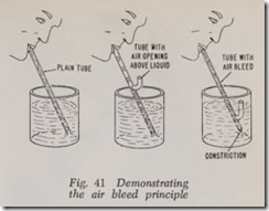
To help break up the fuel into smaller pmticles as they leave the nozzle, the air bleed principle is used in modern carburetors. The principle is demonstrated in Fig. 41. As the liquid is sucked into the tube (left view) it is drawn up in a solid column free of air. If a small opening is placed in the tube above the level of the liquid (center) air bubbles will enter the tube and the liquid will be drawn upward in a continuous series of large drops with air spaces between them. At right, which illustrates the air bleed principle, an air bleed tube with one end open to the air has been set into the main tube at a point below the level of the liquid. Suction on the main tube now intro duces a considerable quantity of air along with the liquid. The constriction in the lower end of the main tube makes the air bleed opening larger, so that the liquid will be more complet ely broken up and mixed with the air as it is drawn upward. A very fine balance of the two openings must be maintained when the air bleed principle is applied to a carburetor.
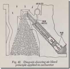
Although design details differ, Fig. 42 shows the general principle of air bleed com_pensation as applied to a carburetor. Air supplied through a bleed hole in the carburetor throat enters the space between the main nozzle and its surround ing tube. With the engine running at medium speed, the difference in the pressure between the air bleed and the nozzle tip forces the fuel level down in the space, tending to uncover the upper bleed holes in the nozzle. Increasing air flow drops the surrounding fuel level still further, uncovering additional nozzle bleed holes. This lowers the suction in the main jet, thereby reducing fuel delivery at the nozzle and preventing the mixture from becoming too rich at high air flows. In normal practice, the sizes of the air bleed, main jet and nozzle are experimentally determined by the engine manufacturer so that the resulting mixture curve supplies the desired fuel delivery charac teristics.
The air bleed serves another important func tion. Since it provides an emulsion of fuel and air in the main nozzle, the response is quicker upon acceleration than would be the case if only gaso line flowed out of the nozzle. Because gasoline is much heavier than air, it would, therefore, lag behind due to its greater inertia.
HOW ALTITUDE AFFECTS CARBURETION
The gasoline in the float bowl is subjected to atmospheric pressure by means of the vent which communicates with the air hom of the carburetor.
But the air rushing through the venturi when the engine is running is reduced in pressure to about half that of atmospheric pressure. This pressure differential which causes fuel flow is dependent on air velocity at the tip of the nozzle, which varies with the volume of air passing through the ven turi. Thus, the weight of the fuel delivered by the fuel metering system is proportional to the volume of air-not its weight.
At sea level, where the air pressure is 14.7 pounds per square inch, one pound of air occupies approximately 13.3 cubic feet. At an elevation of 5,000 feet above sea level, however, the air pres sure is only 12.2 pounds per square inch, so that one pound of air occupies about 15.4 cubic feet. As a result, there is 14 per cent less oxygen by weight in each cubic foot of air supplied to the engine when operating at an altitude of 5,000 feet, and consequently the mixture ratio is richer. Smaller or leaner jets must therefore be used at high altitudes to maintain the desired air-fuel ratios.
CARBURETOR ACCESSORIES
In addition to its primary function of supplying the required air-fuel mixtures for varying engine demands, a modern carburetor usually provides assistance in controlling other features of engine and vehicle operation. These include:
1. A vacuum supply passage for automatic spark advance control (discussed in the Ignition Chapter).
2. Electric switches to operate the starter circuit (described in the Starter Switch Chapter).
3. A dashpot which prevents engine stalling with automatic transmissions by slowing throttle closure.
4. A vacuum-controlled kickdown switch to limit automatic transmission downshift speeds.
TYPES OF CARBURETORS
For the sake of simplicity, the preceding discus sion has been based on a single barrel downdraft carburetor. The same principles apply, however, to updraft and horizontal carburetors.
As the name implies, air flows up through the updraft carburetor, picking up fuel from the nozzle, idle ports, or accelerating jet before being delivered to the manifold. Although this type car buretor was supplanted by the downdraft design for passenger cars many years ago, it still is used on trucks, farm tractors and marine engines.
Like the updraft carburetor, the horizontal carburetor is mounted on the side of the engine. However, air passes horizontally through the carburetor air horn and venturi in a horizontal carburetor before entering the manifold.
Modern eight-cylinder engines carry dual or four-barrel carburetors, the dual carburetor also being used on some six-cylinder engines.
Dual carburetors consist of two primary venturitubes, each containing the necessary parts for a complete carburetor except for a common float bowl. \;vith this arrangement on V-8 engines, each tube supplies air-fuel mixtures to half of the engine’s cylinders. As a result, a V-8 dual carbu retor insures more equal air-fuel distribution.
The four-barrel carburetor is in essence composed of two dual carburetors in a single housing. The primary section forms a complete dual carbu retor, while the secondary section normally incor porates only the throttle valves and fixed idle and main metering systems. During normal cruising, only the primary section supplies air-fuel mix tures. However, when the primary throttles are opened wide, the secondary throttles, controlled by either delayed-action linkage from the primary throttles or air flow through the primary venturis, also open in response to the engine’s demand for more air. Thus, the four-barrel carburetor pro vides more power through better breathing at high speeds, with no sacrifice of fuel economy at low and cruising speeds.
