SWITCHING SYSTEMS
Telephony was invented in the 1870s; all the early exchanges used human operators to establish and supervise calls. As networks grew it became impractical to continue to use people to set up telephone calls. It has indeed been calculated that to carry today’s telephone traffic using 19th century practices would need more than half the total population of all major cities to be employed as telephone operators.
Modern telephones are a far cry from Bell’s original model and even from the ones available a couple of decades ago. They vary in shape and features. They have push buttons instead of dials and memories to store telephone numbers. Some are cordless—the handset is not attached to the base unit, but is linked to it by short range radio. However, the principles of telephony have remained the same from the beginning.
SWITCHING SYSTEM PRINCIPLES
A switching system of some sort is needed to enable any terminal a telephone, a teleprinter, a facsimile unit) to pass information to any other terminal, as selected by the calling customer.
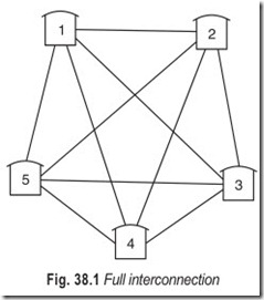
If the network is small, direct links, (Fig. 38.1) can be provided between each possible pair of terminals and a simple selecting switch installed at each terminal. If there are five terminals, each must be able to access four links, so if there are N terminals there must be a total of ½N (N–1) links.
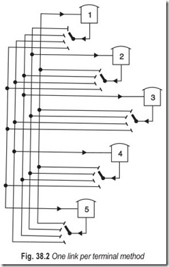
A slightly different approach would be to have one link permanently connected to each terminal, always used for calls to that particular terminal (Fig. 38.2). Again, each terminal would need a selection switch to choose the distant end wanted for a particular conversation, but the number of links is reduced from 10 to 5 for a 5-terminal system, and to N links for N terminals.
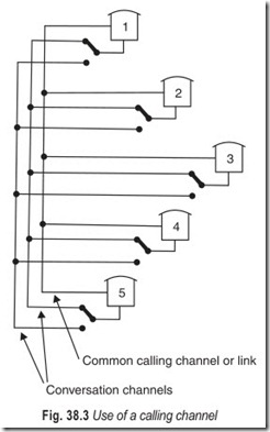
As number of terminals and distances increase, this type of arrangement becomes impossibly expensive with today’s technologies. A variant of this is however in wide use in radio telephone networks : all terminals use a single common channel to give the instructions for setting up each call (Fig. 38.3). The terminals concerned then both switch to the allocated link or channel for their conversation. The number of links may be reduced substantially by this method; enough need to be provided only to carry the traffic generated by the system. But each terminal still needs access to several channels and must have its own selection switch.
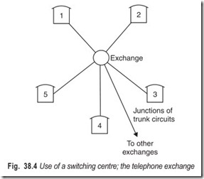
So far as telephone networks are concerned it is at present more economical to perform all switching functions at central points i.e. not to make each terminal do its own switching. This means the provision of only one circuit from the nearest switching point or exchange to each subscriber’s terminal (see Fig. 38.4). As networks grow and expand into other areas more switching points are provided, with special circuits between such points to carry traffic between the areas concerned. The whole network has to be designed to strict transmission parameters so as to ensure that any subscriber on any exchange can converse satisfactorily with all other subscribers, anywhere in the world. Call accounting equipment also has to be provided so that appropriate charges can be levied for all calls made.
The first telephone exchanges were manual and all calls were established by operators. Automatic exchanges using electromechanical relays and switches were however developed very rapidly. Computer- controlled exchanges, with no moving parts at all, are now beginning to become common. Most countries in the world now have automatic telephone systems fully interconnected with the rest of the world’s systems.
UNISELECTORS
For automatic operation the first requirement is a way of indicating the telephone number of the customer to whom you wish to speak. The rotary dial with ten finger holes is now nearly a century old in basic concept but is still in wide use. Contacts within the dial make and break an electrical circuit which interrupts current flowing, from a battery in the exchange, through the loop made by the line to the customer’s premises and through the phone itself. If for example, you dial 6 the dial breaks circuit 6 times with each break lasting a pre-determined time, usually about 1/20th of a second. Relays in the exchange respond to these break signals.
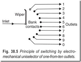
The step-by-step principle was the first automatic system to become practical for public telephone exchanges; the selection of a particular line is based on a one-from-ten selection process. Fig. 38.5 shows a simple switch that has ten contacts arranged around a semicircular arc or bank, with a rotating contact arm or wiper that can be made to connect the inlet to any one of the ten bank contact outlets as required. The wiper is rotated by a simple electromagnet driving a suitable mechanism, so the arrangement is called an electro- mechanical switch. The wiper rotates in one plane only, so this type of electromechnical switch is called a uniselector. Clearly, the inlet can be connected to any one of the ten outlets, but the outlets are numbered from 1 to 0, which is normal practice in the step-by-step switching system.
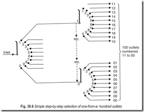
This principle can be extended to enable the inlet to be connected to any one from 100 outlets by connecting each of the ten outlets of the first uniselector to the inlet of another uniselector as shown in Fig. 38.6. The switching of the inlet to any one of the 100 outlets (numbered 11 to 00) is done in two steps, the first digit being selected on the first uniselector, and the second digit being selected on the second uniselector.
If each of these 100 outlets is now connected to another uniselector, the inlet can then be connected to any one from 1000 outlets, numbered from 111 to 000, with the digits being selected one at a time on three successive switching stages. This arrangement can theoretically be extended to accomodate any number of digits in a particular numbering scheme.
TWO-MOTION SELECTORS
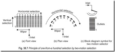
The same sort of numbering scheme can be provided on a step-by-step basis, by a different type of electromechanical switch called a two-motion selector. The principle is illustrated in Figs. 38.7 (a) and (b). The bank of fixed contacts now contains 10 semi-circular arcs, each having 10 contacts, and arranged above each other. The moving contact or wiper can be connected to any one of the 100 bank contacts by first moving vertically to the appropriate level, and then rotating horizontally to a particular contact on that level. The 100 outlets are numbered from 11 to 00. The diagram symbol used to illustrate the 100-outlet two- motion selector is shown in Fig. 38.7 (c).
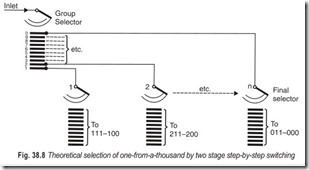
As with the uniselector arrangements, the two-motion selector system can be extended to give access to any number of oulets by adding an extra switching stage for each extra digit required in the numbering scheme. A three digit numbering scheme from 111 to 000 outlets is illustrated in Fig. 38.8 with the one- from-a-hundred selector preceded by a one-froms-ten selector.
In Fig. 38.8, the first digit of the three digit numbering scheme raises the wiper of the first two-motion selector to the appropiate vertical level the selector, then automatically searches for a free outlet on that level to the next selector which caters for the last two digits of the three digit number, as shown in Fig. 38.7(a).
FOUR DIGIT STEP-BY-STEP AUTOMATIC EXCHANGE
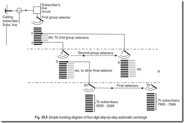
In order to provide access to 10000 lines, a further stage of group selectors is added before the final selectors. Fig. 38.9 illustrates how a calling subscriber can be connected to other subscribers in an exchange having a four digit numbering scheme. Theoretically, a four digit numbering scheme can accomodate 10000 subscribers, but it is necessary also to provide junctions to other exchanges, lines to the operator and other enquiry services, and so on. This means that the capacity of an exchange of this type would in practice be about 6000 subscribers instead of the theoretical 10000.
One of the basic features of step-by-step exchanges is that each selector or switch is conrolled by a group of electro-magnetic relays which is in effect a small brain just sufficient to act on the digit it receives and to route the call to another selector which acts on the next digit, and so on. Each digit dialled takes the caller one step nearer to the called number. In some countries’ step-by-step exchanges and selectors are called Strowger exchanges and Strowger switches.
Most of the group of relays associated wih each selector in a step-by-step system are only used while the call is being set up so, as soon as the appropriate digit has been received and the selector stepped to the particular number dialled, most of these relays are idle. In a main exchange there are likely to be several thousands of these complex selectors, many of them will only be brought into use during busy periods and even the busiest selectors only use all their brains for a second or two every few minutes. It follows, therefore, that a large amount of expensive equipment in such step-by-step exchanges remains idle for most of the time.
Step-by-step selectors are robust and the principles are easy to follow, so fault finding is usually fairly straight forward and faults can be speedily rectified. The selectors do however sometimes introduce an unacceptable level of noise into conversations; they shudder quite violently while the calls are being set up and while they are releasing at the end of each call these movements affect electrical resistance at contact points and so produce noise in circuits.
Selectors have a great many moving parts which means that regular lubrication, with cleaning of relay contacts and readjustment of switches from time to time is absolutely essenial if good service is to be maintained. The high cost of maintenance is one of the main reasons for the fact that electro-mechanical step-by-step exchanges are, in most counries, now being replaced by exchanges which use low-maintenance- cost electronic techniques.
REED RELAY AND CROSSBAR EXCHANGES
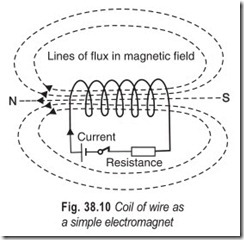
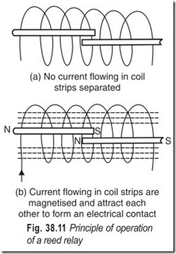
A reed relay is a device based on the fact that an electric current passing through a coil of wire produces an electromagnet, with the ends of the coil having opposite magnetic polarities, as shown in Fig. 38.10.
These two strips can be used to form a switch in another electrical circuit. The two strips are placed inside a glass envelope containing an inert gas, and the overlapping portions are coated with gold to give a good reliable electrical contact. The whole assembly contained by the glass envelope is called a reed insert, since it is placed inside the electromagnet coil.
A typical reed relay has four of these reed inserts placed inside
the electromagnetic coil, each of which can be used to switch a separate electrical circuit. Coils are usually then arranged in amatrix formation so that the contacts in any particular reed relay in the matrix may be operated under the control of pulses of current through winding coils.
Selectors in crossbar exchanges have horizontal and vertical bars operated by electromagnetic relay coils, so that, with a crossbar switch also, the contacts at a particular point in a matrix may be operated under the control of these relays.
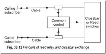
Crossbar switches and reed relays are both used in telephone exchanges. The basic concept is however quite different from that of step-by-step exchanges. Instead of each switch or selector having its own little distributed brain, there is a central brain which controls all switches (see Fig. 38.12).
This central brain or register marker is just like a computer; it registers the number dialled, it checks that the calling number is permitted to make the call, and tests to see if the called number is engaged. Exchanges using this centralised control function are called common control exchanges. If the called number is free, this common control equipment chooses a pass through the exchange to join together the calling line to the called line, and issues instructions to all the crossbar switches or reed relays concerned to operate in such a way that the two lines are connected together. All this happens very rapidly—calls do not have to be switched through the exchange one digit at a time in step with subscriber’s dial. This increased speed of operation means that it becomes attractive to replace ordinary rotary dials by push buttons; these allow calls to be set up very rapidly indeed.
As there is less mechanical complexity in a crossbar or reed relay system, it is more reliable than step- by-step. Also the path through the exchange is such that crossbar switches and reeds introduce less noise into a telephone conversation than step-by-step switches.
Crossbar switches and reed relays have no moving parts demanding regular maintenance and adjustment, so very little routine maintenance is needed and fewer exchange men are required. It is this reduction of maintenance staff which usually results in large common control exchanges being more economic than similar size Strowger step-by-step exchanges.
TRAFFIC HANDLING CAPACITY
Both crossbar and reed relay switching depend on the opeation of a switching matrix, the principle of which can be explained by considering the circuits which are to be connected together as being arranged at right angles to each other in horizontal and vertical lines. These lines represent inlets and outlets of the switch. This idea is illustrated in Fig. 38.13. The intersections between horizontal and vertical lines are called crosspoints. At each crosspoint some form of switch contact is needed to complete the connection between horizontal and vertical lines. This is shown in Fig. 38.14. Any of the four inlets can be connected to any of the four outlets by closing the appropriate switch contacts. For example, inlet 1 can be connected to outlet 2 by closing contact B and inlet 4 can be connected to outlet 3 by closing contact R.
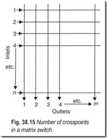
The number of crosspoints in any matrix switch can be calculated by multiplying the number of inlets by the number of outlets (Fig. 38.15). If there are n inlets and m outlets, then the number of crosspoints is (n × m). If n is larger than m (more inlets than outlets), then not all the inlets can be connected to a different outlet. When all the outlets have been taken, there will be some inlets still not in use. If m is larger than n (more outlets than inlets), then when all inlets are each connected to an outlet, there will be some outlets still not in use. So the maximum number of simultaneous connections that can be carried by a matrix switch is given by whichever of the number of inlets or outlets is smaller.
Efficiency in use of crosspoints
Maximum number of crosspoints that
For a large matrix this efficiency is necessarily very low, e.g. a 15 × 15 matrix with 225 crosspoints is only able to use 15 of these at any one time, giving only 6.7% efficiency.
Efficiency can be improved by using smaller matrix switches linked together. Most crossbar and reed relay exchanges are designed on this basis, with a series of interconnected switches. This can, in some circumstances, lead to link congestion or internal blocking. Careful design of the exchange is needed in order to maximise its traffic handling capacity while minimising equipment quantities, and therefore costs.
STORED PROGRAM CONTROL
Conrol in telephone exchanges developed from individual control of each switch on step-by-step exchanges to the use of a small number of complex centralised units in so called common control exchanges, which were mainly crossbar or reed. Common control units were originally completely electromechanical, using the same basic type of relay which had been used for many years in earlier exchanges. Electronic common control had to wait for the popularisation of the transistor and the printed circuit board before it became truly economic.
The use of computers to conrol telephone exchange switching is called Stored Program Control or SPC. This has been defined as the control of an automatic switching arrangement in which call processing is determined by a program stored in an alterable memory.
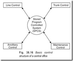
The basic function of an SPC system (Fig. 38.16) is to control line originations and terminations and to provide trunk routing to other central or tandem offices. The SPC system also provided control of special features and functions of a central office, identified here as ancilliary control. The intelligence of an SPC system resided in one processor, and all peripherals were controlled by this single processor. These processors were duplicated for reliability. Control of maintenance functions of the modern digital switching system also evolved from earlier SPC systems. These systems depended heavily on a single processor to conduct all maintenance functions of the switch. Most of the modern digital switching systems employ a separate processor for maintenance functions.
PBX SWITCHING
The acronym PBX (or PABX in Europe) stands for private auomatic branch exchange, a device for switching telephone calls within a building such as an office block or factory. The fundamental principles of PBX switching are the same as those found in a much larger central office switch, which is used in the public network to switch telephone traffic from the caller to the person who is being called. The PBX is essentially a connecting device. When a call comes into the PBX from an outside trunk line, it is either routed directly to telephone extension or to a console with a human attendant. The console rings and is answered by an attendant, who then connects the incoming call to the required extension by dialing the extension number required and, when this is answered, hanging up so that both parties can be connected.
Before PBXs were automated and computerised, the attendant manually connected both the caller and the person being called by physically inserting a cord which contained the incomming call, into a board full of sockets each of which was a designated telephone extension. A modern digital PBX attendant’s console looks much different. Indicator lights on the console display which of the incoming lines is active, which callers are on hold, a display showing which extension the incoming call is being connected to and so on.
Since the early 1970s, PBX technology has moved through a number of distinct technological generations. Early PBXs were entirely electromechanical, using either Strowger or crossbar switching. With the introduction of computers, SPC exchanges replaced electromechanical switching. These PBXs, however, still operated analog switching and transmission, and far from all the PBX functions were compuerised. The next step was to computerise digital switches fully, with all the moving parts replaced by microcircuitry. Future PBX generations will continue the same digital theme, moving toward broadband switching and convergence with local area networks.
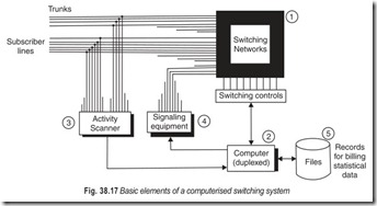
The fundamental elements of a digital PBX are shown in Fig. 38.17. All incoming lines enter some sort of switching matrix (1). Depending on the number of extensions connected to the PBX, there can be hundreds or even thosands of different switching paths to which the incoming call may be connected. The paths within the switching matrix are controlled by a central processor (computer (2)). Each extension line must be constantly scanned for activity (3) and the processor alerted, when activity occurs. The central processor must be informed when a user wishes to place a call as the telephone is picked up. When the number has been dialed, the processor must be able to read the required number and make the connection internally or if it is a call outside PBX, the processor must allocate it an outside line. Similarly, when a caller replaces the telephone handset after the call is finished, the processor needs to be informed that this extension is now free to accept further calls. There are also various signals which must be sent down the line, such as busy signals, signals to make the phone ring, on hook/off hook, dialing and so on. The signaling equipment (4) is controlled as a subset of the central processor. Finally, information about each call, its duration, the number called, and so on, needs to be gathered for accounting and analysis (5).
A ditigal PBX can handle both voice and data traffic and be programmed to support many different functions and applications. The capacity of a PBX to process calls and undertake the other functions that may be required of it is a function of the capability of the central processing unit. Microprocessor technology expands ever upward, and eventually it will be possible to put almost, all the functions of a PBX on to a single microchip. A digital PBX exhibits all the attributes of a computer. It is prorammable and, therefore software controlled has few moving parts, and is highly reliable, it is expandable, can perform extensive test and diagnostic routines, and is intelligent.
FUNCTIONS OF A SWITCHING OFFICE
The basic functions performed by a switching office are the same, whether it is manual, electromechanical, or electronic. The basic stages that a call must go through are as follows :
1. When the subscriber picks up her telephone, the office must detect that service is needed. In an automatic office, the dialing tone is switched to that line, and the mechanism waits for the subscriber to dial.
2. The dialed telephone number must now be used to set up an interconnection path. The number is received as a train of pulses from a rotary dial or a train of frequency pairs from a push-button telephone. These signals cause the equipment to set up a path through the exchange to the appropriate outgoing line.
3. A central office with 10,000 lines would need approximately 50 million interconnections if there were to be a unique path between every input and every possible output. The switches therefore concentrate the calls into a limited number of paths through the exchange. Also, the office will be connected to a limited number of trunks, and again the incoming calls are concentrated onto these outgoing lines. The calls, having been concentrated onto the available interconnections, find their way to the requisite part of the exchange and are switched to the appropriate output lines.
4. The required output line might be busy. It is, therefore, necessary to detect a busy condition and to notify the caller of it. Similarly, as there is only a limited number of paths through the exchange, the exchange itself may not be capable of making the connection and again the caller must be notified. If the exchange is unable to make a connection, it will switch a busy signal onto the caller’s line.
5. It is necessary to make the telephone of the called person to ring. The terminating automatic exchange sends a ringing signal down the line when the connection is made.
6. The telephone of the called party has now rung. The ringing signal must be removed from the line when that person answers. The exchange may, after a respectable wait, disconnect the call.
7. When the call is successfully established and completed, the parties put their telephones down and the circuit must then be disconnected. The exchange circuitry detects that the telephones are back on their rests. The exchange disconnects the circuit freeing the interconnection paths.
8. Last, the caller usually has to be charged. In an exchange there must be some mechanical way of recording the number of calls each subscriber makes and the duration and distance of trunk calls. Some exchanges have counters for each subscriber, which must be read periodically. Computerised exchanges produce magnetic tape for processing on another computer.
HANDS FREE PHONES VS SPEAKERPHONES
Most electronic telephones have a feature called hands free. These telephones have a small speaker that serves as a receiver if the phone is on hook. After pushing a button to access a line, dial tone is heard in the speaker. If the phone is taken off hook, the receiver of the handset will replace the speaker. Thus you can listen to the progress of a call being established through either the handset or the hands free speaker. The speaker will allow you to hear the called phone ringing. You will also hear the voice of the called party when he or she answers, but that person cannot hear you through the speaker. You must speak into the transmitter of the handset. A hands free telephone allows you to place a call without picking up the handset, but once the call is connected, you must talk into the transmitter of the handset.
Some people erroneously think that the speaker on a hands free telephone will also transmit your voice, but it will not. It is hands free in a receive mode only. The telephone that will transmit and receive in hands free mode is called a speaker phone. The speaker phone has a speaker, that acts as a receiver and also has a small transmitting device usually placed on the front edge of the telephone. You can recognise the location of this transmitter. It will be covered by the case of the telephone. The case has two to three small slits in the plastic housing to allow voice signals to reach the transmitter. The hands free telephone allows you to listen without lifting the handset, whereas the speaker phone allows you to both talk and listen without lifting it. Some speaker phones have electronic circuitry to detect when the user is talking. If the person is not talking, the transmitter output is very low. When the transmitter detects a voice, it reduces the output of the speaker. The operation of this electronic circuit prevents feedback to the speaker and eliminates squealing from it.
FEATURE PHONES AND ANSWERING MACHINES
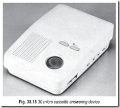
When additional features have been added to the basic single-line telephone, such as last number redial, the phone is called a feature phone. The feature phone has a microprocessor and memory contained in the telephone but is still powered by the standard 52 V dc voltage from the central exchange. This electronic phone can be designed to include special features such as an answering machine. The answering machine uses an electronic solid state ring detector, which signals the microprocessor on each ring received. The microprocessor will count the number of rings received and can be programmed to answer on two or four rings, or not answer at all. The answering machine also includes a DTMF (Dual Tone Multi Frequency) receiver chip. The owner can call ino the answering machine from a remote location and use the DTMF dial, at the remote location, to provide directions to the answering machine. The directions are usually given by sending two digits as a code. The DTMF receiver in the answering machine receives the tones sent by the DTMF dial and is programmed to provide a specific function depending on the code received.
When the answering machine answers a call it is programmed to look at the first code as a password. If it receives the correct password it will honour any additional functions requested. These functions can include any one of the following; turn on the machine, turn off the machine, playback all messages, playback only new messages, record a new announcement, fast forward, fast reverse, rewind, change the password, and so on. The use of DTMF tones to signal the answering machine allows a person to perform any administrative function on the machine from any remote location. The machine has programming that will automatically answer an incoming call, wait for and recognise a password code, return a record announcement, respond to DTMF signals and intepret the received code and perform the function assigned to that code.
EXERCISES
Descriptive Questions
1. What is the need for a switching system?
2. With the help of a suitable sketch, briefly explain the working of a selecting switch.
3. Explain the significance of central points and exchange.
4. Write short notes on :
(a) Manual exchange (b) Automatic exchange
(c) Computer-controlled exchange (d) Call-accounting equipment
(e) Step-by-step principle (f) Uniselector
5. Explain the difference between a rotary-dial telephone and a push-button telephone.
6. With the help of a suitable sketch, explain the principle of switching by electromechanical uniselector of one-from-ten outlets.
7. Differentiate between a uniselector and a two-motion selector.
8. Explain a three-digit numbering scheme with the help of a two-motion selector.
9. What are the features of step-by-step selectors?
10. List the drawbacks of step-by-step electromechanical exchanges.
11. Explain the principle of operation of a reed relay.
12. What are the advantages of crossbar system?
13. With the help of a suitable sketch, explain, the principle of switching by a 4 × 4 matrix switch.
14. Define and explain stored program control (SPC).
15. Explain PBX switching.
16. With the help of a suitable sketch explain the basic elements of a computerised switching system.
17. What are the functions of a switching office?
18. Differentiate between a hands free phone and a speaker phone.
19. How does an answering machine operate?
20. What role is played by DTMF tones in answering machines?
Fill in the Blanks
1. A switching system enables any terminal to pass information to any other terminal as ………………………. by the calling customer.
2. So far as telephone networks are concerned, it is more economical to perform all switching functions at ………………………………..
3. The whole of the telephone network has to be designed to strict………………………. parameters so that any subscriber on any exchange can converse satisfactorily with all other subscribers anywhere in the world.
4. The wiper rotates in one plane only, so this type of electromechanical switch is called a ………………………. .
5. In a two-motion selector, the wiper first moves………………………. to the appropriate level, and then rotates………………………. to a particular contact on that level.
6. Each digit dialed takes the subscriber one step………………………. to the called number.
7. A large amount of expensive equipment in step-by-step exchanges is………………………. most of the time.
8. Elecromechanical step-by-step exchanges have a high cost of………………………. .
9. Exchanges using a register marker are called………………………. exchanges.
10. A crossbar exchange is more………………………. than a step-by-step exchange.
11. Very little………………………. is needed in crossbar exchanges.
12. Fewer………………………. men are required in crossbar exchanges.
13. The intersections between horizonal and vertical lines are called………………………. .
14. Efficiency can be improved by using smaller matrix switches………………………. together.
15. The use of computers to conrol telephone exchange………………………. is called stored program control.
16. The PBX is essentially a………………………. device.
17. A digital PBX can handle both voice and………………………. traffic.
18. The speaker phone allows you to both………………………. and………………………. .
ANSWERS
Fill in the Blanks1. selected |
2. central points |
3. transmission |
|
4. uniselector 7. idle |
5. vertically, horizontally 8. maintenance |
6. nearer 9. common control |
|
10. reliable 13. crosspoints 16. connecting |
11. maintenance 14. linked 17. data |
12. exchange 15. switching 18. talk, listen |
