ENGINE CONSTRUCT ON
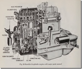
The foundation of a water-cooled engine is a piece of cast iron which is called the cylinder block. This casting usually includes the upper half of the crankcase. Bolted to the top of the block is a cylinder head which is usually made of cast iro .
The oil pan, which is made of pressed steel, IS bolted to the bottom of the cylinder block. The crankcase on a modern car consists of two por tions: ( 1) the upper half which is an integral part of the cylinder block and (2) the lower half which is the oil pan just mentioned.
The block contains cylindrical holes which are correctly called cylinders, although the terms bar rels or bores are often used and are almost equally descriptive.
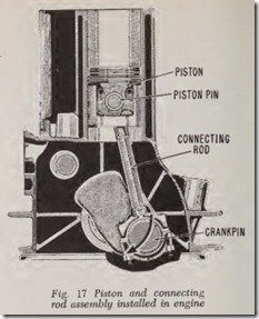
Plungers called pistons move up and down in the cylinders. The motion of the pistons is trans mitted to the crankshaft by means of the connect ing rods which are pivoted at their upper ends to the piston pins in the pistons, Fig. 17. The lower ends of the connecting rods are attached to crank pins on the crankshaft.
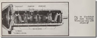
The crankshaft rotates in main bearings, Fig. 18, which are attached to the upper half of the crankcase.
It should be noted that the up and down mo tion of the pistons is transformed into rotary mo tion of the srankshaft by means of the connecting rods.
The rotary motion of the crankshaft is transmit ted to the flywheel which in turn rotates clutch, transmission, propeller shaft, rear axle shafts, wheels and tires. The horizontal thrust of the tires against the road pushes the car.
CORVAIR ENGINE CONSTRUCTION
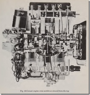
As shown in Fig. 19, this engine is the hori zontal opposed air-cooled six-cylinder type. The cast aluminum alloy crankcase is vertically di vided into two halves which are held together by bolts at the parting line. Each crankcase half has three pilot openings for individual cast iron cylin ders which are positioned to the opening by means of four long studs at each cylinder. These studs pass through holes in the cylinder cooling fin structure and cylinder head and serve to secure the cylinders and head to the crankcase.
The two opposing cylinder heads are made of aluminum. The heads incorporate cooling fins, built-in intake manifolds, wedge-shaped eombus tion ehambers, and valves for each cylinder. The valves are aetuated by push rods through stamped roeker arms.
Steel tubes are used to house the push rods in the open area between the crankease and eylinder heads adjaeent to the cylinders. These tubes serve to proteet the exposed push rods as well as drain back oil from the cylinder heads to a relatively shallow oil pan bolted to the bottom of the erank ease.
The camshaft, whieh actuates the push rods through hydraulie valve lifters, is nested between the two halves of the erankcasc below the erank shaft. This camshaft differs from the eonventional
in that each of the three exhaust valve cam lobes are twice the width of the intake valve cam lobes and aetuate a pair of exhaust valve lifters. The eamshaft journals ride directly on the maehined base metal of the erankcase.
No separate main bearing eaps are required sinee the four bearings are supported entirely by the crankease halves.
The engine rear housing mounts to the rear of the erankcase over four long studs. This housing contains the oil pump, crankshaft seal and pri mary oil passages. It provides the mounting for the distributor and the generator adapter to whieh the fuel pump, oil fill pipe, generator, oil filter and idler pulley are mounted. A reetangular erankease cover mounts to the top of th e crankcase and forms a base for the centrifugal blower.
VALVE SYSTEM
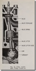
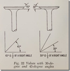
All m odern Amer ican car en gines h ave valves which are opened by a cam on the camshaft , Fig. 21 and closed by a spring. These valves are called poppet valves because they pop up to open and pop down to close. The angle between th e seat and the valve is usually 45 degrees, although on a few engines it is 30 degrees, Fig. 22.
The intake valve, when it is opened, connects the carburetor with the cylinder; when the ex haust valve is opened it connects the cylinder with the exhaust passages from manifold to mu ffier. All passenger cars currently produced have one in take valve and one exhaust valve per cylinder.
Valves may be located in the cylinder block , Fig. 21, or in the cylinder head, Fig. 20. If the valves are located in the cylinder block, the engine is called an L-head design because the combus tion space roughly resembles an inverted L when the piston is at lower dead center. The valves are opened by cams acting directly on tappets which push against the valve stems.
If the valves are located in the cylinder head, the engine is called an overhead valve engine.
With two recent exceptions, this type of engine has long push rods at the side of the block which operate rocker arms that push the valves open.
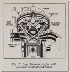
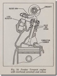
The exceptions are the Jeep overhead valve engine, Fig. 23 and the Pontiac Tempest overhead valve engine, Fig. 24. These engines have the camshaft on top of the cylinder head. The cams act directly on the rocker arms which in turn push the valves open. This design is known as an over head valve overhead camshaft, or simply over head camshaft engine.
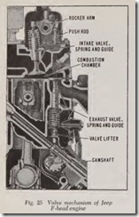
Still another type of engine is the so-called F head, Fig. 25. From a common camshaft in the crankcase, the intake valves are overhead, oper ated by push rods and rocker arms, and the exhaust valves are in the L of the cylinder block, operated by tappets or valve lifters.
CYLINDER HEAD GASKETS
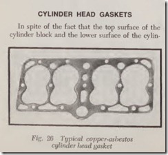
In spite of the fact that the top surface of thecylinder block and the lower surface of the cylinder head may be smooth to the eye, the two surfaces never fit together closely enough to pre vent leakage. Therefore a layer of rather soft flexible material, called a gasket, must be inserted between them. There are various designs. The cylinder head gasket, Fig. 26, consists of a layer of asbestos fibre encased in thin sheet copper.
This cylinder head gasket has sufficient resil iency so that it seals the cylinder head to the block while its sheet copper casing is able to withstand the high temperature and pressure of the combus tion chamber. Steel-asbestos gaskets of this type are also used.
In anoth er design, a sheet of steel is sandwiched between two layers of asbestos fibre, Fig. 27. There are prongs sticking out of both sides of the steel sheet which hold the asbestos layers securely in place.
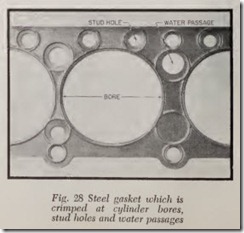
In still another design, the asbestos is eliminated. A thin sheet of steel is crimped as shown in Fig. 28, and then coated with a special lacquer cement on both sides. Special gasket cements are often used with the other cylinder head gaskets mentioned.
