A Simple Mechanically Controlled Servo System
A simple servo system can be constructed by a simple spool valve and a hydraulic jack. This is shown in Fig. 7.1. The hydraulic high pressure is connected to the middle port of the spool valve. The other two ports are connected to the return path to the hydraulic power supply. The configurations shown in the diagram both inlet valves to the jack are closed and the load is at rest. The mechanical connections between points A, B, and C are used to control the position of the load. When the point B is moved by amount e, the jack will not move because the two ports at both ends are closed. Therefore, the point A on the spool valve will move by amount x. The spool valve moves to the right. The high pressure oil flows to the left hand side of the piston and the load starts moving to the right.
The position of point B is fixed when it is moved by amount e. As the load moves to the right, the point A moves to the left and spool valve moves to its original po- sition and the high pressure port will be closed again and the load stopped at the desired position.
Using the principle of superposition, a relation between the three displacements x, e, and y may be obtained.
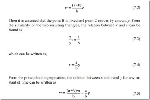
First, it is assumed that the point C is fixed and the point B is moved by amount e. As a result of the displacement of point B, the point A moves by amount x. From the similarity of two triangles, the relation between x and e can be found in Eqs. (7.1) and (7.2).
In this calculation, it is assumed that the distance AB = a and distance BC = b
The second term is taken as negative because when y is moved, x moves in the op- posite direction of x positive.
Equation (7.5) shows that there is a mechanical feedback. It means that when an input of e is applied, the mass moves with the amount y until x becomes zero. In fact, the displacement e can be calibrated in terms of displacement y. The point B can be moved between points A and C. The location of point B in fact changes, as will be shown later, the gain of the system. It also changes the calibration of the displacement y. If the point B is moved above point A, then the connection between the spool valve and hydraulic jack must be changed so as to have a position control system.
Designing such a system, the stability and accuracy of the system must be studied. This is achieved by deriving a mathematical model for each part of the system and deriving the overall transfer function which relates the displacement y to the input displacement e.
When the spool valve is displaced by x, the flow equation becomes
where Cd is the valve coefficient which is function of valve parameters such as cross sectional area, oil density, and the gravitational acceleration and the shape of the valve. The manufacturer of valves must provide these parameters. Ps, p are the supply pressure and the pressure on the side of the jack. Equation (7.6) is nonlinear and it is proportional to displacement x and square root of the jack pressure. Using the linearization technique Eq. (7.6) may be written as
The reader must be aware that the lower case variables represent variation from an operating point. This has not been implemented in Eq. (7.6) because it is clear that the equation represents the absolute values of the flow rate.
The pressure forces the piston to move according to the equation of motion of
In Eq. (7.8), M is the total mass of moving parts of the jack, A is the cross sectional area of the piston, and C represents the viscous friction that the numerical values must be given by manufacturers. The reader must know that s is the Laplace Trans- form operator and is the same as differentiation with respect to time assuming that all the initial conditions are zero.
On the other hand, the flow equation from the spool valve assuming that the oil is incompressible moves through the jack according to the equation,
where, C1 is the leakage coefficient and it is proportional to pressure difference p across the piston and p is the pressure variation. The first term in Eq. (7.9) is the flow rate required to move the piston by the speed (sy).
Eliminating the variables p, q, and x and with some algebraic manipulation, the overall transfer function becomes
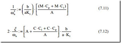
Equation (7.10) represents a second-order transfer function which was discussed in detail in previous chapters. The natural frequency which represents the speed of response is given by the coefficient of s2 in the denominator and the damping ratio is given by the coefficient of s in the denominator. As was discussed in the previous chapters, the important behavior of second-order transfer functions is stable but the damping ratio might become very small resulting in excessive oscillations. From the following equations, the natural frequency and damping ratio can be obtained.
Electrohydraulic Servo Valves
It can be seen that the damping ratio increases as the leakage and viscous friction increases. The mass of total moving parts reduces the natural frequency. The only parameter that can vary to obtain the desired behavior is the distance (a) and (b).
The reader is encouraged to obtain the overall transfer function by doing the algebraic manipulation to ensure that the transfer function is correct.
In deriving the transfer function (7.10), it was assumed that the oil is incompressible. When the mass has to move with high speed, the oil compressibility cannot be ignored and in fact it may have a dominant contribution to the response. In this case, the compressibility of oil must be considered. This makes the transfer function of third-order and stability becomes an important issue. The effect of oil compressibility will be discussed in the next section and in similar way can be implemented in the flow equation. The reader is encouraged to derive the transfer function of the servo system discussed in this section after reading the next section.
The flexibility of the transmission mechanism may be necessary to be considered in some very high performance applications. The procedure is the same as was derived for DC servo motors. In this case, it is recommended to use state space form for governing differential equations. This can be done without deriving the overall transfer function which enables that the state variables may be used as feedback. The mechanical controller discussed in this chapter may be replaced by electrohydraulic servo valves. This will be discussed in the next section.


