When you learned to read, you were first taught a set of symbols that represented different sounds. This set of symbols is called the alphabet. Schematics and wiring diagrams are the written language of motor controls. Before you can learn to properly determine the logic of a control circuit, you must first learn the written language. Unfortunately, there is no actual standard used for motor control symbols. Different manufacturers and companies often use their own sets of symbols for their in-house schematics. Also, schematics drawn in other countries may use entirely different sets of symbols to represent different control components. Although symbols can vary from one manufacturer to another, or from one country to another, once you have learned to interpret circuit logic it is generally possible to determine what the different symbols represent by the way they are used in the schematic. The most standardized set of symbols in the United States is provided by the National Electrical Manufacturer’s Association, or NEMA. These are the symbols that we discuss in this chapter.
Push Buttons
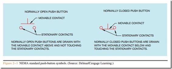
One of the most used symbols in control schematics is the push button. Push buttons can be shown as normally open or normally closed (Figure 2 – 1). Most are momentary contact devices in that they make or break connection only as long as pressure is applied to them. The pressure is generally supplied by someone’s finger pressing on the button. When the pressure is
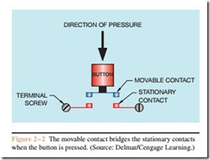
removed, the button returns to its normal position. Push buttons contain both movable and stationary contacts. The stationary contacts are connected to the terminal screws. The normally open push button is characterized by drawing the movable contact above and not touching the stationary contacts. Since the movable contact does not touch the stationary contacts, there is an open circuit and current cannot flow from one stationary contact to the other. The way the symbol is drawn assumes that pressure will be applied to the movable contact. When the button is pressed, the movable contact moves downward and bridges the two stationary contacts to complete a circuit (Figure 2 – 2). When pressure is removed from the button, a spring returns the movable contact to its original position.
The normally closed push-button symbol is characterized by drawing the movable contact below and touching the two stationary contacts. Since the movable contact touches the two stationary contacts, a complete circuit exists and current can flow from one stationary contact to the other. If pressure is applied to the button, the movable contact will move away from the two stationary contacts and open the circuit.
Double Acting Push Buttons
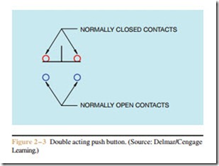
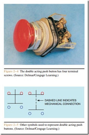
Another very common push button found through- out industry is the double acting pushbutton (Figure 2 – 3). Double acting push buttons contain both normally open and normally closed contacts. When connecting these push buttons in a circuit, you must make certain to connect the wires to the correct set of contacts. A typical double acting push button is shown in Figure 2 – 4. Note that the double acting push button
has four terminal screws. The symbol for a double acting push button can be drawn in different ways (Figure 2 – 5). The symbol on the left is drawn with two movable contacts connected by one common shaft. When the button is pressed, the top movable contact breaks away from the top two stationary con- tacts, and the bottom movable contact bridges the bottom two stationary contacts to complete the circuit. The symbol on the right is very similar in that it also shows two movable contacts. The right-hand symbol, however, connects the two push-button symbols together with a dashed line. When components are shown connected by a dashed line in a schematic diagram, it indicates that the components are mechanically con- nected together. If one component is pressed, all those that are connected by the dashed line are pressed. This is a very common method of showing several sets of push-button contacts that are actually controlled by one button.
Stacked Push Buttons
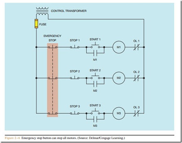
A very common connection employing the use of multiple push buttons is shown in Figure 2 – 6. In this ex- ample one stop button, referred to as an emergency stop button, can be used to stop three motors at one time. Push buttons that contain multiple contacts are often called stacked push buttons. Stacked push buttons are made by connecting multiple contact units together that are controlled by a single push button (Figure 2 – 7).
Push-Pull Buttons
Another push button that has found wide use is the push-pull button (Figure 2 – 8). Some push-pull but- tons contain both normally open and normally closed contacts much like a double acting push button, but the contact arrangement is different. This push-pull button is intended to provide both the start and stop functions in one push button, eliminating the space needed for a second push button. The symbol for a push-pull button of this type is shown in Figure 2 – 9. When the button is pulled, the normally closed contact remains closed and the normally open contact bridges the two stationary contacts to complete the circuit. When the button is released, the normally open contact returns to its normal position and the normally closed section re- mains closed. When the button is pushed, the normally closed section opens to break the circuit and the nor- mally open section remains open. A schematic diagram showing a push-pull button being used as a start-stop is shown in Figure 2 – 10.
Push-pull buttons that contain two normally open contacts are also available (Figure 2 – 11). These but- tons are often used to provide a run-jog control on the same button. When this is done, the run function is gen- erally accomplished with the use of a control relay, as shown in Figure 2 – 12 (page 16). When the button is pressed downward, a circuit is complete to M coil, causing all open M contacts to close and connect the motor to the power line. When the button is released, the contact reopens and de-energizes M coil, causing all M contacts to reopen and disconnect the motor from the power line. When the button is pulled upward, it completes a circuit to CR relay, causing both normally open CR contacts to close. One CR contact connected in parallel with the run section of the button maintains power to CR coil when the button is released. The CR contact connected in parallel with the jog section of the button closes and energizes M coil, causing the motor
to be connected to the power line. The motor will con- tinue to run until the stop button is pressed.
Push-pull buttons that contain two normally closed contacts can be obtained also (Figure 2 – 13, page 16). These buttons are generally employed to provide stop for two different motors (Figure 2 – 14, page 17). When the button is pulled upward, the connection to the two top stationary contacts is broken, causing coil M1 to de-energize. The bottom section of the button remains closed. When the button is pressed, the top section re- mains closed and the bottom section opens and breaks the connection to coil M2.
Regardless of the configuration of the push-pull buttons or how they are employed in a control circuit, they are generally used to provide the function of two different buttons in a single space. They are a good choice if it becomes necessary to add controls to an existing control panel that may not have space for extra push buttons.
Lighted Push Buttons
Lighted push buttons are another example of pro- viding a second function in a single space (Figure 2 – 15, page 17). They are generally used to indicate that a motor is running, stopped, or tripped on overload. Most lighted push buttons are equipped with a small transformer to reduce the control voltage to a much lower value (Figure 2 – 16, page 18). Lens caps of different colors are available.
Related posts:
Incoming search terms:
- motor connection with push button
- Why normally open push button used on motor
- function of the normally open contact connected in parallel with a star-button?
- motor control single push button
- One of the methods of electrical interlocking is accomplished with the use of double-acting push buttons
- purpose of push button in motor control
- push button used to on the motor
- the difference between start push button and emergency push button diagram
- what is the function of the normally open contact connected in parallel with a start button
- Double acting push button application
- how to select push button for motors
- how to determine number of contacts for push button
- how the local control push button for motor
- function of push button in circuit to control electric motor
- function of double acting push button
- function of a stop button on a motor
- emergency push button connection
- double push button symbols
- double acting push button definition
- why push button is used in starting a motor
