Electronic Concepts: More Interesting Than You Think
Some Basic Stuff You Really Need to Know
INTRODUCTION
You don’t have to be an engineer, physicist, or mathematical genius to learn electronics. But there are a few basic things that you need to know so you can understand what is going on in the circuits and equipment. For example, you need to know that electrons are what makes up current flow, and voltage is what makes the current flow. You also need to know about magnetic fields and electric fields, where they come from, and what they do. And how mag- netism and current flow are related. With that background you are ready to learn about the various components and circuits. This chapter takes care of those basics.
ELECTRICITY AND ELECTRONICS
Electricity is a type of energy produced by a charge that is either fixed (static) or moving (dynamic). The main source of electricity is the electron, a sub- atomic particle that has a negative charge. When electrons are stored or moved, electricity is produced.
Electricity is one of our prime sources of energy. It is used for lighting, heat- ing, and operating appliances of all sorts. It powers motors to produce mechanical energy, and it powers our electronic equipment. The uses of electricity are virtually infinite.
Electronics is the field of applied science that uses components such as resistors, capacitors, diodes, transistors, and integrated circuits to control and process electricity. These components are used to create circuits that convert, modify, vary, translate, or otherwise manipulate electrical charges to perform useful functions. That is the essence of it. Now for the details.
Atoms and Electrons
This section really ought to be called Physics 101 but I don’t want to scare you away. Just to make you more comfortable, I have to say that it is not all that complicated or difficult to understand. So even if you avoided physics in high school, just be aware that it is pretty easy. Trust me.
All matter, whether it is a solid, a liquid, or gas, is made up of tiny enti- ties called atoms. An atom is the smallest possible particle of substances called elements. An element is a chemical substance that cannot be subdivided into smaller, simpler substances. Typical elements are hydrogen, oxygen, gold, sil- ver, copper, carbon, helium, silicon, and sodium. All matter is either an element or composed of several elements. Atoms of two or more elements often com- bine to form new substances called compounds. For example, water is a com- pound of hydrogen (H) and oxygen (O) or H2 O. Salt is a compound of sodium (Na) and chlorine (Cl) or NaCl. The smallest possible particle of a compound that exhibits all the characteristics of the substance is called a molecule.
According to the theories of physics, an atom is composed of a nucleus consisting of a core of tightly bound subatomic particles, called protons and neutrons. Protons have a positive charge. Neutrons are neutral, having neither a positive nor a negative charge.
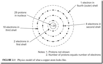
Rotating around the nucleus are electrons. The electrons arrange them- selves in multiple orbits in much the same way that the planets orbit around the sun. The orbits are sometimes referred to as rings or shells. Electrons have a negative charge. Figure 2.1 illustrates a copper atom. The number of elec- trons in orbit equals the number of protons in the nucleus. The number of positive charges equals the number of negative charges. Therefore, the atom is balanced electrically.
As far as electronics is concerned, the most important part of an atom is its electrons. Since electrons can be manipulated (i.e., stored or moved), they can be used to produce electricity. This electricity can then, in turn, be processed and controlled to perform a wide range of valuable functions. By applying an external force, the electrons in the outer shells can be stripped off to produce current flow.
Charge, Voltage, and Current
There are two basic types of electricity, static and dynamic. Static electricity is the buildup of a charge between two objects. Dynamic electricity supplies a continuous charge.
Static Electricity
With static electricity, one object has an excess of electrons and the other has a shortage of electrons. The object with an excess of electrons is therefore nega- tive while the object with a shortage of electrons is positive. A basic law of electricity states that opposite charges attract and like charges repel. The two oppositely charged bodies, one negative and one positive, will have a high physical attraction for one another. An invisible force field called an electric field will exist between the two charged objects. The object with a shortage of electrons attracts the object with excess electrons.
The two oppositely charged objects will naturally attract one another. The closer they are, the greater the attraction. This attraction of the charges sets up an electrical force field between the two bodies. This electric field, like a mag- netic field, contains energy that can be released to perform useful work.
Whenever there are opposite charges on two objects, we say that an elec- trical potential or difference of potential exists between them. This difference of potential is called voltage. Voltage is an electrical pressure that can cause work to be accomplished.
The charge stored on the two objects is usually called static electricity because it is stationary. However, this charge is usually dissipated in some way. If the two charged objects get too close, or the charge builds up too high, the attractive force becomes so great that the electrons jump the gap between them and create a spark. That is how lightning occurs. The clouds and the earth become oppositely charged, the earth positive, the clouds negative. The charge becomes so great that the electrons leap across the free space gap, ionizing the air and creating a path through which the electrons travel to neutralize the
positive charge on the earth. The result is the massive spark or flash that we call lightning and the roar we call thunder.
In general, static electricity is not very useful. It represents energy stored as a charge, but it quickly dissipates as a spark or a brief flow of electrons between the negatively and positively charged objects when the two charged objects get close enough or when the charge gets too high. We call this an electrostatic dis- charge (ESD). Static electricity, or ESD, is regarded as more of a disadvantage or nuisance than anything else. In fact, it is one of the main causes of damage to electronic components such as transistors and integrated circuits.
Neutralizing a charge between two objects cancels or eliminates the poten- tial. However, if we had a constant charge that could constantly be replenished, we would have a continual source of potential (voltage) and could therefore sustain a flow of electrons. With such a source of electrical energy, useful work can be accomplished.
Dynamic Electricity and Current Flow
Electricity as we know it, whether in electrical power applications or in elec- tronics, is actually the flow of electrons. Electrons flowing from one place to another is known as current flow. And it is voltage that causes the current to flow. When electrons flow, we have energy that can be put to practical use. Electrons flowing in a filament create light. Electrons flowing in a heating coil produce heat. Electrons flowing in a motor produce mechanical energy. The object is to convert the energy from one form to another. In electronics, we precisely control the electrons with special components and circuits to produce a variety of effects.
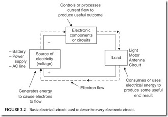
Figure 2.2 provides a general block diagram model that shows how all electrical or electronic circuits work. A voltage source produces the energy that causes electrons to flow. This current flow is controlled or processed by a single electronic component, or many components that make up an electronic circuit. The processed electrons flow through a load that consumes or uses the electrical energy to produce a useful output. In an electrical application, the load may be a light, a heating element, or motor, as described above. In an electronic application, the load may be an antenna that radiates the radio signal produced by the electronic circuits. Or the load may be the magnetic head that develops and records digital data on a hard disk or a laser that records a video signal on a DVD.
A couple of key facts about the circuit in Figure 2.2 are required here. First, there must be a voltage source to cause the current to flow. The electrons flow from the negative terminal of the voltage source around the circuit as they are attracted by the positive terminal. Second, the circuit must always form a com- plete loop from plus to minus.
Current is so important that we need some way to measure it. We do this by standardizing the number of electrons that move past one point in a conductor
during a specific period of time. The charge or quantity of electrons (Q) is measured in coulombs (C). One coulomb of charge is equal to 6,242,000, 000,000,000,000 or 6.242 X 10¹⁸ electrons. If 1 coulomb moves past a point in 1 second, we say that the current is 1 ampere (A). One coulomb per second (1 C/s) equals 1 A.
Direction of Current Flow
The current flowing in electronic components and circuits consists of electrons that are influenced by a charge or voltage source. The early pioneers of elec- tricity did not know that electricity was the movement of electrons. They knew that there was some kind of movement, of a charge or current, but they did not know what it was, or in which direction it flowed. In order to explain elec- trical phenomena and perform analyses of components and circuits, they simply assumed a direction of current flow that everyone agreed to and used. Their origi- nal assumption was that current flowed from positive to negative, the opposite of the actual direction. This has become known as conventional current flow.
Even after the discovery that real current was electrons moving from negative to positive, scientists and engineers continued to assume a positive-to-negative current flow. And science and engineering professors have continued to teach and support the conventional current flow concept. Most science and engineering textbooks illustrate and teach conventional current flow. Old traditions die hard, or maybe never die.
As it turns out, it does not really matter what direction current flows. Any analysis, design, or explanation can be successfully carried out using either elec- tron flow or conventional current. One way is not any better than the other in
Direction of Current Flow (Continued)
describing or understanding electrical or electronic phenomena. Why academia has perpetuated the myth of conventional current flow rather than accepting and teaching the truth is not known. It no doubt stems from long-time heritage, cus- tom, and convention.
Conductors, Insulators, and Semiconductors
A conductor is a material that has many electrons easily freed up by an exter- nal voltage. Current flows through conductors easily. They have what we call low resistance. Most good conductors are metals like copper, silver, or alu- minum, with loosely bound electrons that can be freed by an external volt- age to create current flow. Copper wire is the most commonly used conductor because of its low cost and its ability to be formed into many different shapes and sizes. Most metals are conductors but so is salt water.
Insulators are just the opposite of conductors. These are usually compounds in which the electrons are tightly bound together with the nuclei of the atoms. Even with lots of voltage applied, the electrons are hard to strip away to make current. Insulators keep current from flowing. Some common insulator materi- als are glass, ceramic, and plastics.
A third category of material is called semiconductor. It is a material that can be changed to make it a good conductor or a good insulator or anything in between. Semiconductors are used to make the transistors, diodes, and inte- grated circuits. The most common semiconductor is silicon. Others are ger- manium and carbon. Compounds such as gallium arsenide (GaAs), indium phosphide (InP), and silicon germanium (SiGe) are examples. Most integrated circuits (ICs) or chips are made of silicon.
MAGNETISM
You are probably asking, what does magnetism have to do with anything? As it turns out, it has lots to do with electricity and electronics. As you will see, the two are tied together significantly, meaning you need to know about both to get the big picture. Magnetism is essential to all electrical and electronic phenomena. Without magnetism, there would be no electricity or electronics.
Magnetic Fields
Magnetism is an invisible force that has the power to attract pieces of iron, or alloys of iron such as steel. Iron, steel, and the metals nickel and cobalt are called magnetic materials because they can be magnetized to generate a mag- netic field, or they support the development and passage of a magnetic field. Magnets are pieces of such materials that exhibit this force. Magnetism has no effect on nonmagnetic materials such as other metals (aluminum, brass, etc.), or on objects made of wood, plastic, or glass.
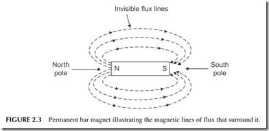
You have no doubt experienced the effects of magnetism yourself. You may have played with a horseshoe magnet as a kid, or used bar magnets like the one in Figure 2.3 in a school lab. And you most likely have used flat magnets to hold paper notes on your refrigerator or file cabinet. These are called perma- nent magnets because they retain their magnetic force indefinitely.
A magnet is surrounded by an invisible magnetic force field made up of magnetic lines of force or flux lines. These flux lines flow out of one end of the magnet, the north (N) pole, and into the other end, the south (S) pole, as shown in Figure 2.3. The ends of the magnet are the points of the heaviest con- centration of the magnetic field.
The basic law of magnetism follows: opposite poles attract, and like poles repel. When you get two permanent magnets together, the north and south poles will attract one another. On the other hand, two north poles will repel one another. Two south poles will also physically push away from one another. Permanent magnets are used in a variety of electrical and electronic equip- ment. Their most common use is in motors, where the attraction and repulsion of magnets create rotary motion.
Electromagnetism
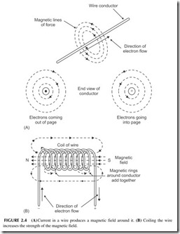
Magnetism is also produced by electricity. Whenever electrons flow in a con- ductor, they produce a magnetic field. This effect is called electromagnetism. Figure 2.4A shows how the magnetic lines of force encircle a wire through which current is flowing. Note that the direction of the lines of force depends on the direction of the current flow.
The strength of the magnetic field around a wire depends on the magnitude of the current flowing. High current (composed of many electrons) produces a strong magnetic field. Despite the current amplitude, however, the magnetic field weakens because it spreads out quickly, even at a short distance from the wire.
If you make a coil out of the wire, as shown in Figure 2.4B, the lines of force around each turn are added together. The result is that a more powerful,
highly concentrated magnetic field is produced. In fact, the coil simulates a bar magnet with north and south poles.
As indicated earlier, the strength of the magnetic field depends on the cur- rent amplitude in the wire. High current produces a strong field. The magnetic field is also increased by coiling the wire, which helps concentrate the lines of force. The closer the turns of the wire, the stronger the field. You can also increase field strength for a given current level by simply adding more turns
to the coil. Strong electromagnets are made by tightly coiling together many turns of fine wire in several layers.
Another way to increase the strength of the magnetic field is to insert a bar or core of magnetic material inside the coil. Because flux lines flow easier in iron or steel than in air, an iron or steel bar inside the coil helps concentrate the lines of force. Most of the flux lines flow through the core because it repre- sents a lower path of resistance than the surrounding air for the lines of force. The result is a very strong field.
Electromagnetic Induction
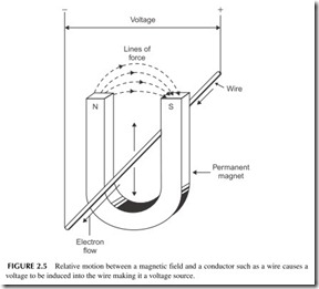
Another important principle of magnetism is electromagnetic induction. This principle states that whenever there is relative motion between a conductor and a magnetic field, a voltage will be induced into the conductor.
Refer to Figure 2.5. If the wire is moved up or down so that it cuts through the magnetic lines of force between the magnet poles, voltage will be induced in the wire and cause current to flow. Voltage will also be induced into the wire if the wire is held in a fixed location and the magnetic field is moved so that
the flux lines cut across the wire. The wire actually becomes a voltage source. That voltage will cause current to flow. The direction of current flow in the wire depends on both the direction of the magnetic field and the direction of the relative motion between the magnetic field and the wire.
The amount of the induced voltage depends on the number of flux lines cut and the speed of cutting. The greater the number of lines of force, the higher the induced voltage and the greater the current flow. The highest induced volt- age occurs when the conductor cuts across the flux lines at a right angle. If the wire moves parallel with the lines of force, no voltage is induced.
The induced voltage can also be increased by coiling the wire. More turns passing through the magnetic field will produce greater induced voltage and current flow. The motion in the magnetic field causes a small voltage to be induced into each turn of wire. All of the voltages will add together to produce a higher voltage.
In the examples above, we have assumed that the magnetic field comes from a permanent magnet. However, it doesn’t really matter where the field comes from. An electromagnetic field works just as well. Electromagnetic induction is the principal method of generating electricity in the world. Most electrical power is produced by giant generators containing large coils of wire that rotate in a magnetic field. The generator or alternator in your car works the same way.
VOLTAGE SOURCES
To make current flow, we must have voltage. That voltage will produce either direct current (DC) or alternating current (AC). DC is electron flow in only one direction. AC is current that flows in one direction and then reverses and flows in the opposite direction.
DC Voltages
DC may be a fixed, steady current, one that varies, or one that switches off and on periodically. A DC voltage source is one that causes direct current to flow one way through the circuit, component, or conductor. It has positively and negatively charged terminals of a fixed polarity. It always causes electrons to flow from negative to positive.
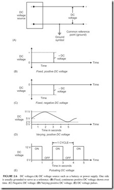
Figure 2.6A shows a fixed, positive DC voltage source, which is usually either a battery or an electronic power supply. We call it a positive source because the negative terminal of the DC source is connected to a common point called the ground. The other terminal is positive with respect to ground. Voltages are always looked at or measured between two points with one point (ground) being the reference. The polarity of the voltage is the polarity of the terminal not connected to ground.
The remainder of Figure 2.6 shows graphs of DC voltage over time. In electronics we normally view DC or AC voltages with respect to time. The positive DC voltage is shown in Figure 2.6B as a horizontal dashed line.
A negative DC voltage is shown in Figure 2.6C. The dashed line represent- ing the voltage below the zero line indicates that it is negative. The voltage is negative with respect to the reference point known as ground.
Figure 2.6D shows a varying positive DC voltage. It begins at +5 volts, rises upward to +11 volts, and then drops to +2 volts over a period of 5 sec- onds. The left-hand scale indicates the voltage level.
Figure 2.6E shows a pulsating DC, that is, one that turns off and on. This voltage switches on to +12 volts, stays on for 1 second, and then switches to zero for 1 second. Then this on–off cycle repeats. One cycle is the time of one ON pulse and one OFF pulse or in this case 2 seconds. Such pulse signals are usually called binary or digital signals.
AC Voltages
As its name implies, AC current flows in two directions in a conductor, com- ponent, or circuit, but not at the same time. The electrons move in one direc- tion, then reverse and flow in the other direction, both for a short period of time. The direction of flow reverses repeatedly.
The polarity of an AC voltage reverses periodically. During one period, the terminals of the voltage source are + and -, but later reverse to – and +. This reversal continues to repeat as the voltage amplitude varies. Since it is the voltage that causes current to flow, if the polarity of the voltage changes, then naturally the direction of the electron flow will also change periodically. The electrons just flow back and forth in the circuit.
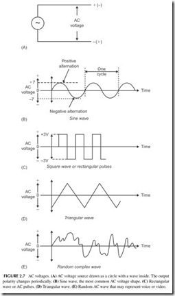
An AC voltage source is usually represented by just a circle with a varying wave inside as illustrated in Figure 2.7A. It may be the AC outlet in your home, a signal generator, or a type of electronic circuit called an oscillator. AC voltages and currents can assume many shapes. The most common electrical and electronic AC voltage is a sine wave, as shown in Figure 2.7B. The voltage rises gradually from zero to a positive peak, and then drops to zero. Then it reverses polarity, rises to a negative peak, and returns to zero. Each rise and fall is called an alternation. One positive and one negative alternation form a cycle. The cycles repeat over and over. The number of cycles that occur per second is called the frequency.
The AC power-line voltage that comes into your house and appears at the outlets is a sine wave. Its frequency is 60 cycles per second (cps). The term hertz (abbreviated Hz) is normally used instead of cps to express frequency. The power-line frequency, therefore, is 60 Hz. All radio signals are sine waves, but have very high frequencies.
AC signals can have a variety of other shapes as well. Figure 2.7C shows a square or rectangular wave. It is made up of pulses of alternating polarity volt- ages that switch from +6 to -6 volts. Figure 2.7D shows a triangular wave, and Figure 2.7E, a complex waveform that might represent voice or video. Regardless of their shape, AC signals have one thing in common: they reverse the polarity and direction of current flow periodically. Their frequencies can range from a fraction of a cycle per second to billions of cycles per second.
AC Frequency
Frequency is measured and expressed in units called cycles per second (cps) or Hz. Hertz is the more common unit. To express higher frequencies, the units kilohertz (kHz), megahertz (MHz), and gigahertz (GHz) are used.
1 kHz = 1000 Hz
1 MHz = 1 million Hz or 1000 kHz
1 GHz = 1 million Hz, 1 million kHz, or 1000 MHz
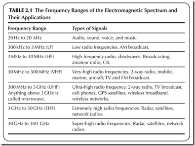
Table 2.1 presents a summary of various frequency ranges that you will encounter and the types of signals in those ranges.
AC Voltage Measurement
To measure or represent the amount of AC in a circuit, we usually state the peak, peak-to-peak, and root mean square (rms) values. The peak value of a wave is simply the voltage measured from the zero line to the maximum posi- tive (or negative) value. In Figure 2.7B, the peak value of the sine wave (Vp) is 7 volts. The peak-to-peak value, normally abbreviated Vpp , is the positive peak added to the negative peak. Or, since the positive and negative peaks are identical in a sine wave, the peak-to-peak value is two times the peak value, or in this case 14 volts.
Vpp = 2Vp
Another way to measure AC voltage is to use an average value known as the root mean square (rms), or effective value. The rms value is computed by multiplying the peak value by 0.707, or:
Vrms = 0.707 Vp
Thus, the rms value of the sine wave is 0.707 X 7 = 4.949 volts. Most sine wave voltages are measured and stated in terms of the rms value. The amount of AC voltage available at a standard AC outlet, for example, is 120 volts rms. The rms value as discussed above is applied only to sine waves. The signifi- cance of the rms value is discussed later when we address power.
PRACTICAL DC AND AC VOLTAGE SOURCES
Just what is the source of DC and AC? Such voltages originate from a variety of sources.
DC Voltage Sources
Batteries
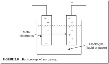
The most common source of DC voltage is a battery. A battery is a collection of cells. A cell is the basic unit of voltage generation that creates electricity by chemical action. A battery is made up of two or more cells connected together. Figure 2.8 shows the configuration of a cell. It consists of two metal electrodes immersed in a solution called an electrolyte. The chemical interaction between the metal electrodes and the electrolyte produces a separation of charges. This separation of charges results in an excess of electrons on one electrode (the – terminal of the cell) and a shortage of electrons on the other electrode (the + terminal of the cell). If a conductor is connected externally between the termi- nals, electrons will flow from – to +
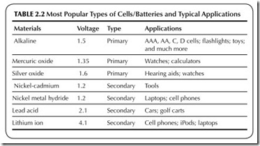
The amount of voltage produced by the cell depends on the type of elec- trodes and the electrolyte. Various chemical combinations generate different voltages. Table 2.2 lists the most commonly used cells and the voltage they generate.
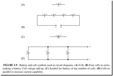
The schematic symbol of a cell is illustrated in Figure 2.9A. To create a battery, two or more cells are connected together. The cells are usually con- nected in series form, that is, end to end and – to +, as shown in Figure 2.9B. The cell voltages add up to produce the total battery voltage. For example,
six small alkaline cells are connected in series to create a 1.5 X 6 = 9-volt transistor-radio battery. A car battery consists of six lead-acid cells connected in series; each produces 2.1 volts for a total battery voltage of 6 X 2.1 =
12.6 volts. If four nickel-metal-hydride cells are connected in series, as in Figure 2.9B, the total battery voltage is 4.8 volts.
The simplified schematic symbol for a battery is shown in Figure 2.9C. Instead of drawing all of the individual cells, the simplified battery symbol is used.
The cells listed in Table 2.2 can be separated into two categories, primary and secondary. Primary cells cannot be recharged. As the chemical action produces voltage, the electrodes and electrolyte are actually used up. At some point, no further chemical action is produced, and no voltage is generated. The cell must be discarded and replaced.
Secondary cells, on the other hand, can be recharged. In these cells, the chemical action can be reversed by connecting an external DC voltage to the bat- tery. This is called charging. Charging forces electrons into the battery, produc- ing a reverse chemical action that rejuvenates the electrodes and the electrolyte. The cell can be discharged and charged repeatedly, giving it a very long life.
The amount of current that can be drawn from a cell depends on its size and the quantity of the materials used. Large electrodes and electrolytes can produce more current, but the voltage stays the same; the type of material, not its volume, determines voltage.
For example, a large D-size flashlight cell and a tiny AAA penlight cell are both made of alkaline material so their output voltages are both 1.5 volts. The D-cell, however, can produce more current and will have a longer life because it is larger.
A greater current capacity can be obtained by simply connecting two or more cells in parallel. In a parallel connection, the cells are wired across one another, all + leads connected together, and all – leads connected together, as shown in Figure 2.9D. The output voltage remains the same, but the current output can be higher.
Solar Cells
A special type of voltage-producing cell is the so-called solar cell. Also called a photovoltaic (PV) cell, a solar cell converts light into electrical energy. When the sun or artificial light shines on the cell surface, a voltage is generated. The most commonly used material is silicon, and a typical cell generates about
0.5 volt. Other materials, such as cadmium sulfide and gallium arsenide, are also used.
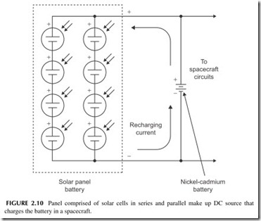
You have probably seen solar cells used in hand-held calculators. Big arrays of solar cells are now being adopted as an energy source for homes and businesses. Another important application is spacecraft. Virtually every satel- lite, deep-space probe, or other space vehicle, uses solar cells for power. Huge panels of solar cells connected in a complex series–parallel array produce
a powerful battery that can operate all electrical and electronic equipment on board. Typically, however, such a solar battery is primarily used to recharge the main spacecraft power source, which may be a nickel-cadmium second- ary battery, as shown in Figure 2.10. The voltage produced by this array is 2 volts.
Fuel Cell
A fuel cell is a special type of battery that combines oxygen and hydrogen gas to produce voltage and electron flow. That means you have to have a supply of hydrogen gas, which is usually stored in a bottle or other container. Typically, the oxygen can be extracted from the air, but if not you will need a bottle of oxygen as well. When you combine the two, charges separate and plus and minus termi- nals are formed. Most fuel cells generate between 0.5 volt and 0.9 volt, so you have to put many of them in series to be useful. Usually they are bulky and incon- venient because of the need for the gases. But as long as oxygen and hydrogen are supplied, the fuel cell produces the voltage. Heat and water are by-products of the chemical process, making them essentially impractical for many applications.
Power Supplies
Electronic circuits require a source of DC for proper operation. A great many electronic products are still powered by batteries because they are small and portable, such as cell phones, iPods, and the like. Other electronic equip- ment is designed to operate from the AC power line. Such equipment contains an electronic power supply that converts AC into the required DC voltages. Computers, TV sets, and other nonportable electronic equipment have an AC power supply.
AC Voltage Sources
Generators
The AC that appears at the outlets of our homes and offices is produced by huge electromechanical generators owned and operated by an electrical util- ity company. A source of mechanical power—such as water, or a steam tur- bine powered by oil, coal, or nuclear fuel—operates the generator. The turbine converts steam into mechanical energy to turn the generator. The genera- tor rotates coils in a strong magnetic field to produce a voltage. The speed of rotation of the coils determines the frequency. That voltage is a 60-Hz sine wave.
The big wind generators popping up across the landscape also produce AC sine waves, but because the rotational speed depends on the wind speed, the AC frequency will vary, which is unacceptable. Therefore, the AC voltage they produce is converted to DC, and then back into AC of the correct frequency (60 Hz) to be used or put on the AC power grid.
Another example is the alternator in your car. “Alternator” is just another word for an AC generator. The alternator, driven by the car engine through a belt, produces AC output that is converted to DC by diodes making up a recti- fier. The rectifier output is DC to charge the battery.
Inverters
Electronic circuits called inverters are used to produce AC from a DC source. This is common in solar power systems. The solar cells produce DC, which keeps batteries charged. The DC is then converted to AC by the inverter.
In electronic equipment, AC signals are generated by circuits called oscil- lators or function generators. The AC signals are sine waves, square (rectan- gular) waves, or triangular waves, among others.
Analog and Digital Signals
You have no doubt heard the terms “analog” and “digital.” These terms distin- guish between the two main types of voltages or signals in electronic equip- ment. Analog signals are voltages that vary smoothly and continuously over time. You saw some in previous figures. Analog signals may be either DC or
AC. A continuous DC voltage is analog, as well as a varying DC signal. A sine wave and the random signal in Figure 2.7E are also analog signals.
Analog signals come from microphones, video cameras, and sensors that detect light level, temperature, and other physical conditions. The most com- mon types of analog signals are voice or music from a microphone and video from a camera.
Digital signals are pulses or on–off signals. The DC pulses in Figure 2.6E and 2.7C are digital. Most digital signals are binary in nature, meaning they only have two voltage values. In Figure 2.6E the two values of voltage are +12 and zero volts. In Figure 2.7C the two voltage levels are +3 and -3 volts.
You will see both analog and digital signals in all sectors of electronics. Today, most signals are digital. Special circuits called analog-to-digital con- verters (ADC) and digital-to-analog converters (DAC) are used to translate between the two types of signals.
Fourier Theory and the Frequency Domain
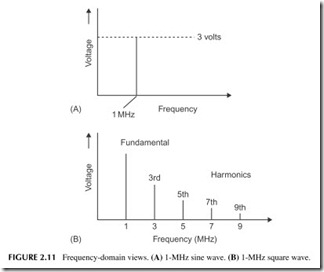
We normally think of electronic signals as voltages that vary over time. Waveforms showing signals are said to be in the time domain. Time is the hori- zontal axis in a graph. But there is another way to look at signals in the fre- quency domain where frequency is on the horizontal axis. For example, a sine wave is shown as a single vertical line at its frequency as Figure 2.11A shows. The height of the line is representative of the voltage level, either peak or rms.
The big question is, how do you show a complex signal like a square wave in the frequency domain? The only way to do this is to use the Fourier theory that says that any complex nonsinusoidal wave is made up of a group of sine waves added together. There is a fundamental sine wave that occurs at the signal fre- quency plus harmonic sine waves. A harmonic is a sine wave whose frequency is an integer (whole number) multiple of the fundamental sine wave. The second harmonic of a 50-MHz sine wave is a 100-MHz sine wave. The third harmonic is a 150-MHz sine wave and so on. If you add the fundamental sine wave to mul- tiple harmonics of differing amplitudes and phases, you can create any shape of wave.
For instance, a square wave is made up of a fundamental sine wave and all the odd harmonics. A 1-MHz square wave is made up of a fundamental 1-MHz sine wave and harmonics of 3 MHz, 5 MHz, 7 MHz, and so on. According to Fourier theory, it takes an infinite number of harmonics but in reality only a few (like up to the fifth or seventh) are needed to approximate the square wave. The frequency domain plot of a square wave therefore would look like the one in Figure 2.11B.
When looking at a time domain view of a signal, try to keep a frequency- domain picture in mind at the same time. You cannot actually see the third or fifth harmonics in the time domain plot but they are buried in there just the same.
Project 2.1
Getting Familiar with a Multimeter
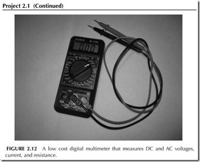
One of the things you are going to need as you work with electronic parts, circuits, and equipment is a multimeter. This is a test instrument that measures voltage, current, and resistance. Some also measure capacitance and other things. These multimeters are usually hand held and battery operated. There are two basic types, analog and digital. Analog meters use a dial to show the measured value. Digital multimeters (DMMs) have a liquid crystal display (LCD) to show the measurement. See Figure 2.12 . The two types work equally well; which one you use is typically a matter of preference for meters versus digital displays. I recommend a digital unit.
The good news is that multimeters are not expensive. You can get one for as lit- tle as $10, but a better unit may cost you several times that. The cheaper units are kits that you will need to build yourself. I do not recommend a kit if you are just starting out. Later in this book I will discuss kits in more detail. In any case, you need to buy a multimeter and learn to use it. Plan to buy one as soon as you can. Check your local Radio Shack store or buy online.
Three good sources of multimeters by mail order or web order
follow: Elenco Electronics: www.elenco.com
Jameco: www.jameco.com
Kelvin Electronics: www.kelvin.com
Project 2.2
Hardware Sources
As an electronic experimenter, you should be familiar with buying parts and equipment. Radio Shack stores still stock some parts but today most hobbyists and experimenters buy via the mail or online. The most popular sources of parts and equipment are All Electronics, Digi-Key, and Jameco. And you will discover others. You can go to their websites, but you really should get on their mailing list and get a catalog. Do that as soon as you can. Links to these sources follow. You can get your multimeter from one of them as well.
All Electronics: www.allelectronics.com Digi-Key: http://www.digikey.com Jameco: http://www.jameco.com
Ramsey Electronics: http://www.ramseyelectronics.com
Project 2.3
Magazines of Interest
As you are learning electronics, you need to be continuously aware of what is going on in the industry and with the technology. Magazines are a good source of that information. One that you should read on a regular basis is Nuts & Volts .
Project 2.3 (Continued)
available at some newsstands and bookstores, but if you cannot locate it, go to the website and subscribe. This magazine has lots of articles and columns, including construction projects. It is a great way to stay up to date and learn more. Nuts & Volts also publishes Servo magazine, which is aimed at people who like to build and play around with robots.
Another recommended magazine that has an embedded controller emphasis is Circuit Cellar. This publication contains great educational articles and projects. Get a subscription if you are serious about learning more.
Another interesting magazine is called Make—it is not strictly electronics but it usually contains some good electronic projects. It also features other mechanical projects such as robots, among other things. This one is definitely worth a look the next time you are at the newsstand.
Nuts &Volts and Servo: www.nutsvolts.com Circuit Cellar: www.circuitcellar.com Make: www.makezine.com
Project 2.4
Measuring Voltages
A good first step in using a multimeter is to measure voltages. Batteries are a good place to start. Look around the house and locate some batteries that you com- monly use. Take them out of the equipment before you measure them. You will most likely find AA or C cells. Set the multimeter to measure DC according to the meter user’s manual and connect the test leads to the battery. The red lead is +, the black lead is -. The LCD on the meter should show the voltage. It should be
1.5 volts. You can also check batteries in some cordless phones, cell phones, or other devices. You may be able to remove the battery from a laptop. In each case, check to determine the battery technology—lithium ion, alkaline, and so on.
Two key points to remember. First, if you get the test leads reversed, the red to the – terminal of the battery and the black to the + terminal, the meter will read a negative value. That just means that the leads are reversed, nothing more. Second, you cannot typically judge the condition of the battery by measuring its voltage. With no load on the battery, no current is drawn from it so you are just measuring the characteristic voltage. If you connect the battery to something, cur- rent will flow and its voltage will decrease slightly. If it decreases a lot, the battery is going bad. If the cell or battery voltage is several tenths of a volt lower than the characteristic value given in Table 2.2, the battery is probably bad.
You could also go out to your car and measure its battery voltage. Be careful. You cannot get shocked but you could short something. When the engine is off, the battery will probably register about 12 volts. With the engine running, the bat- tery voltage will be a bit higher, as much as 15 volts or so. The generator is charg- ing the battery, making its voltage a bit
Project 2.4 (Continued)
One last thing: you can use the multimeter to measure the AC line voltage at an outlet. Only do this if you have probes that will fit into the slots on the outlet.
And be super careful as you can kill yourself. Be paranoid, even.
Set the multimeter for AC voltage at an appropriate level of at least 120 volts, according to the multimeter manual. Place the probe tips into the AC outlet and read the voltage.
Do NOT touch any metal with the probe tips!!
Your value will depend on things like how far you are from the power station, what appliances and other items are on, and time of day. In any case, the voltage range is about 95 to 130 volts. It is rarely lower than 110 or higher than 125 volts. The typical value is 120 volts, or what is called nominal. I measured mine at 117 volts.
