Cool nights and hot days
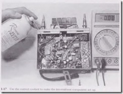
A coolant can help to locate thennal intermittence in transistors, ICs, resistors, capacitors, and SMD components. By applying several coats of coolant on a suspected part, sometimes one can make the internlittent component act up or return to its natural state. Coolant sprayed directly on transistors, ICs, capacitors, and SMD parts can locate the intermittent component. Choose a coolant that will not leave a residue or harm the plastics on PC boards (Fig. 1-17).
The no-residue cleaner or flux remover is especially effective in removing activated fluxes, dirt, and other ionic contanlinants found on PC boards. Flux cleaner is ideal for
use on electronic equipment, PC boards, relays, and soldered connections. Most flux spray cans leave no residue and will not harm plastics.
Choose a superwash spray that thoroughly removes dirt and grease from parts and assemblies. A can of wash can be used on tape heads, motors, relays, and PC boards.
Superwash head cleaner safely removes carbon deposits, oil, dirt, nicotine, dust,and other contaminants. The spray is ideal for sensitive magnetic and optical pickup heads. Clean cassette tape head and CD devices with head and disc cleaner. Choose a tuner chemical that cleans and lubricates corroded contacts. This spray will improve Switch-type tuner performance and reliability. Choose a tuner spray that will not harm plastics and is not conductive.
Sometimes by applying heat to the body of an intermittent capacitor, transistor, or IC, the component might began to act up. A little heat from a soldering iron or gun close to the part can do the trick. Choose a portable hair dryer or heat gun to blow hot air· directly on the suspected component. A heat gun with a flexible tube can blow hot air directly on the part without damage to other components. Applying heat and coolants to intermittent components can make them act up and solve a very tough intermittent symptom.
Double trouble
Here we are not talking about chewing gum when two or more components are defective within a TV, VCR, or cassette player. Often the electronic chassis has only one trouble symptom and one defective component. When you repair one problem and another appears, this is double trouble. Sometimes you may find more than two defective components in one section of a TV chassis.
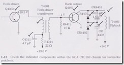
For instance, the RCA CTC 169 chassis was dead, and this was caused by a over heated horizontal output transistor (Q4401). After replacing the output transistor, the chassis was still dead. A defective capacitor (C4402, 0.47 f-µF, 400 V) was located with the ESR meter. Finally, before the chassis came to life, IC4401 was replaced. All these components had to be replaced before the TV chassis was repaired (Fig. 1-18).
Lightning damage
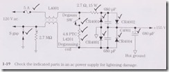
when a lightning- or storm-damaged chassis appears on the service bench, look for many damaged components. Power line outage conditions can damage any electronic product co1mected to the ac line. A direct hit can cause the unit to be totaled out. Often lightning damage comes in through the antenna or ac power cord and destroys components within these sections.
Look for burned or damaged antenna coupling capacitors and scorched cable wiring and terminals. A damaged ac receptacle and power cord and damaged line voltage regulator circuits in a TV chassis can result from lightning or power outage damage. Carefully check the entire PC wiring for pulled or lifted sections. After all repairs are completed, let the chassis run for several days before returning it to the cabinet (Fig. 1-19).
Down below
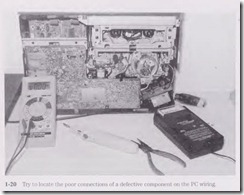
Do not forget to look underneath the chassis for defective boards, connections, and components. Look for possible overheated terminals, brown board areas, and poorly soldered connections on the PC board wiring side. These areas will show overheated parts and intermittent connections. Check the terminals on the component side to locate a possible defective component (Fig. 1-20).
Burned or stripped PC board wiring might indicate defective components, a power surge, or lightning damage. Several different blown-off areas of PC board wiring might indicate lightning damage. Often this means that the chassis is totaled and that complete set replacement is required.
Cracked or damaged boards might be visible by looking closely with a magnifying glass. A strong light above the board, with light showing through the board, can help locate fine cracks in PC board wiring. A magnifying circle light is ideal for PC board wiring inspection. Going from terminal to terminal with the low-ohm scale of a digital multi meter (DMM) might help to locate open PC board wiring. The ESR meter is great in locating broken PC wiring.
Outside the chassis
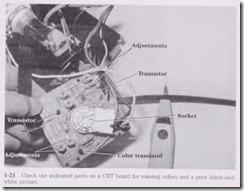
Often a separated PC board might be found mounted horizontally on a TV chassis and can show broken contacts where the board is coru1ected to the main board chassis. In the latest high-powered car radios you will find several PC boards stacked on top of one another. You may have to remove several boards, soldered ground coru1ections, and cable coru1ections to get to the board that contains the defective component. A color symptom in a TV might result from a bad board or con1ponent on the CRT board out side the TV chassis (Fig. 1-21).
Check for defective con1ponents outside the regular chassis when all other tests are normal. For instance, a horizontal white line or no vertical Sweep might be caused by an open winding or poor connection of the yoke assembly. Red missing from the raster might be caused by a defective color transistor or R-Y circuit located on the CRT socket board. Look outside the regular circuits when all other tests fail.
Do it today, not tomorrow
Do not set that “tough dog” product aside for several weeks before you attempt to repair it. Callbacks or electronic products returned for the second tin1e can be put off until tomorrow, but tackle the “tough dog” problems at once. Often the repair time involved may be less than 1 hour. Don’t put off today and do it tomorrow. It may never get done.
When you have repaired a boom-box cassette player for distorted sound and the unit is returned with another problem such as the cassette player is now eating tape, make another charge. Of course, the customer is angry because the repair lasted only a few days. Any electronic technician knows that the sound distortion problem is a long way away from the mechanical tape-eating symptom.
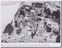
However, did you clean the tape heads, capstan, and pinch roller while the player was in for repair (Fig. 1-22)? Sometimes we forget to do preventive maintenance. A good cleanup and a thorough preventive maintenance check can save a lot of headaches. Besides a good cleanup, you should check the type of cassette and the condition of the suspected cassette, which may be defective. The custon1er is never wrong, but he or she may not know how cassettes operate or may mishandle the cassettes.
Intermittent problems
Intermittent service problems take a lot of service time to locate the defective component. The intermittent symptom might even turn into a “tough dog” problem . When TV audio cuts up and down, check the audio circuits on through to the loud speaker. An intermittent loss of color and intermittent shrinkage of vertical height at the top and bot tom of the screen in a RCA CTC177 chassis might result from poorly soldered joints in the tuner. Although the color and vertical components are miles apart, so to speak, this service problem does occur.
The TV chassis that starts up and intermittently shuts off can be the result of poorly soldered joints on the horizontal driver transformer. A TV that intermittently shuts down but then turns back on and goes through auto programming can be the result of badly soldered joints on the shielded cover of the microprocessor. Intermittent bright ness and height and audio volume that varies in a TV can be caused by badly soldered connections on an SMD resistor.
Intermittent symptoms must be isolated to a certain section within the electronic product. The intermittent component can be located with signal-tracing methods, volt age monitoring, and ·waveforms taken with an oscilloscope (Fig. 1-23). Isolate the defective part when the intermittence occurs by taking critical voltage tests. Spray coolant and apply heat to help make the intermittent part act up. Remember that the intermit tent part might operate normally for days and the next hour start cutting up and down. Intermittence troubleshooting can be tough.
Time is precious
Time is one of the most important factors for the electronics technician. Time marches quickly when you are stuck with a difficult problem and no schematic. It might take months to receive the correct diagram and sometimes never on some older products. Wasted time is wasted dollars.
Servicing a radio or stereo chassis might require more time for a TV technician . Some TV technicians were not trained for audio-type service. Time can be wasted and never recovered when working on a “tough dog” problem. In the following pages I hope to reduce the time it takes you to troubleshoot and repair consumer electronic products without a schematic.
Test points
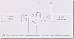
You will find many different tests points within a TV, CD player, or VCR player to take signal, waveform, and voltage measurements. If you can find the various test points in a given section, the circuits can be monitored for easy servicing. The test points might only consist of a lug, spot, or raised area that any test instrument can be connected to .
The test points with in a CD player provide quick attachment of the scope for troubleshooting and making critical adjustments. Test points are found throughout cam corder circuits for adjustments, waveforms, and testing procedures. The test points in a TV chassis may be located in the video, radiofrequency/intermediate frequency (RF/IF), autokinne bias, and central processing unit (CPU) circuits (Fig. 1-24).
Say it isn’t so
Have you ever checked the electronic chassis, ordered a new part, waited for the new replacement, installed it, turned on the switch, and the results are the same? This just cannot happen after installing a new IC con1ponent. Look at all the time lost in removing and installing the IC replacement. This can occur to the best electronics technician when all components tied to the terminal of the suspected IC are not checked thoroughly.
What if the voltages measured on each pin terminal of an IC were quite normal with a fairly normal input signal and no output waveform? Even the supply voltage (Vcc) was quite norn1al. The IC just has to be defective. You install a new IC after removing the old one and cleaning up each PC terminal connection. The results are the same-no output signal.
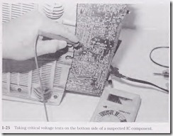
So you again make voltage, resistance, and waveform tests (Fig. 1-25). Every tiling appears normal. Maybe a piece of foil was cracked or broken. All terminal pins are soldered up again. Resistance tests are made from each pin terminal to a common point on the same PC foil. All tests are good. What went wrong?
No doubt the new IC replacement is defective. However, this never happens because you test every component before installing it for this very reason. Of course, it is difficult to test the IC with so many terminals. So you just install it and take a chance. Nine times out of ten you never have to replace a replacement. These operations just happen in the life of an electronics technician. Always test each component before installation.
