Objectives
After studying this unit, the student will be able to:
• Identify terminal markings for two-speed, one-winding motors and controllers
• Describe the purpose and function of two-speed, one-winding motor starters and motors
• Connect two-speed, one-winding controllers and motors
• Connect a two-speed starter with reversing controls
• Recommend solutions for troubleshooting these motors and controllers
Certain applications require the use of a squirrel cage motor having a winding arranged so that the number of poles can be changed by re versing some of the currents. If the number of poles is doubled, the speed of the motor is cut ap proximately in half.
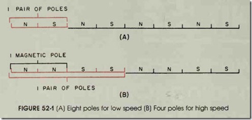
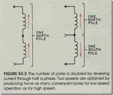
The number of poles can be cut in half by changing the polarity of alternate pairs of poles, see figure 52-1. The polarity of half the poles can be changed by reversing the current in half the coils, figure 52-2.
If a stator field is laid flat (as in figure 52-1) the established stator field must move the rotor twice as far in B as in A and in the same amount of time. As a result, the rotor must travel faster. The fewer the number of poles established in the stator, the greater is the speed in rpm of the rotor.
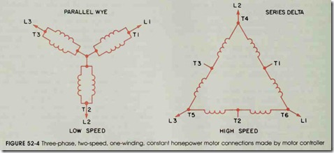
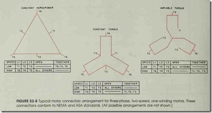
A three-phase squirrel cage motor can be wound so that six leads are brought out, figure 52-3. By making suitable connections with these leads, the windings can be connected in series delta or parallel wye, figure 52-4. If the winding is such that the series delta connection gives the high speed and the parallel wye connection gives the low speed, the horsepower rating is the same at both speeds. If the winding is such that the series delta connection gives the low speed and the par allel wye connection gives the high speed, the torque rating is the same at both speeds.
Consequent pole motors have a single wind ing for two speeds. Extra taps can be brought from the winding to permit reconnection for a dif ferent number of stator poles. The speed range is limited to a 1:2 ratio, such as 600-1200 rpm or 900-1800 rpm.
Two-speed, consequent pole motors have one reconnectable winding. However, three-speed, consequent pole motors have two windings, one of which is reconnectable. Four-speed consequent pole motors have two reconnectable windings.
Referring back to the motor connection table in figure 52-3, note that for low speed operation, Tl is connected to Ll; T2 to L2; T3 to L3; and T4, TS, and T6 are connected together. For high
speed operation, T6 is connected toLl; T4 to L2; T5 to L3; and all other motor leads are open.
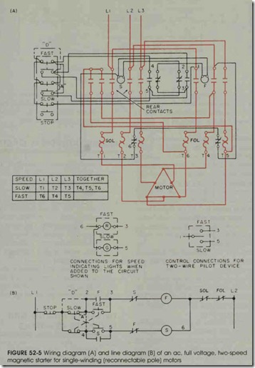
Figure 52-5 illustrates the circuit for a Size 1, selective multispeed starter connected for opera tion with a reconnectable, constant horsepower motor. The control station is a three-element, fast slow-stop station connected for starting at either the fast or slow speed. The speed can be changed from fast to slow or slow to fast without pressing the stop button between changes. If equipment considerations make it desirable to stop the motor before changing speeds, this feature can be added to the control circuit by making connections “D” and “A”, shown in figure 52-5 by the dashed lines. Adding these jumper wires eliminates push-button interlocking in favor of stopping the motor be tween speed changes. This feature may be desir able for some applications.
Connections for the addition of indicating lights or a two-wire pilot device instead of the con trol shown are also given.
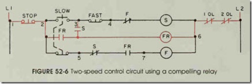
A compelling-type control scheme is shown in figure 52-6. These connections mean that the op erator must start the motor at the slow speed. This controller cannot be switched to the fast speed un til after the motor is running.
When the slow button is pressed, the slow speed starter S and the control relay FR are ener gized. Once the motor is running, pressing the fast button causes the slow-speed starter to drop out. The high-speed starter is picked up through the normally closed interlock contacts S of the slow-speed starter and through the normally open contacts of control relay FR. The normally open contacts of control relay FR will now close.
If the fast button is pressed in an attempt to start the motor, nothing will happen because the normally open contacts of control relay FR will prevent the high-speed starter from energ1zmg. When the fast button is pressed, it breaks a circuit but does not make a circuit. This scheme is an other form of sequence starting.
MISTAKEN REVERSAL CAUTION
When multispeed controllers are installed, the electrician should check carefully to insure that the phases between the high- and low-speed windings are not accidentally reversed. Such a phase reverse will also reverse the direction of mo tor rotation. The driven machine should remain disconnected from the motor until an operational inspection is completed. The upper oil inspection plugs (pressure plugs) in large gear reduction boxes should be removed. Failure to remove these plugs may create broken casings if the motor is reversed accidentally.
Machines can be damaged if the direction of rotation is changed from that for which they are designed. In general, the correct rotational direc tion is indicated by arrows on the driven machine.
TWO-SPEED STARTER WITH REVERSING CONTROLS
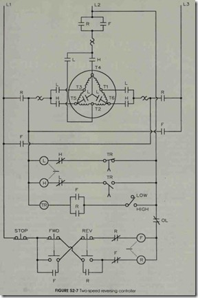
Figure 52-7 is an elementary diagram of a two-speed, reversing controller. The desired speed, either high or low, is determined with a two-position selector switch. The direction of ro tation is selected with either the forward or reverse push buttons. When the power contacts (F) or (R) are closed, current is supplied for the “high-low” controls. Assuming that the selector switch is in the high position, contactor Lis energized to start the motor in low speed. At the same moment, tim ing relay coil TR is energized. When the normally closed delay-in-opening contact TR op ns after a preset time delay, normally open contact (TR) closes at the same time. This operation drops out contactor L, and the normally closed interlock L energizes contactor H. The motor is now at high speed.
The motor may be started in low speed in ei ther direction before it is transferred to high speed. If the low speed is to be maintained, the selector switch is turned to low in order to open the circuit supplying the timing relay coil TR. (This coil would normally transfer the control to high-speed operation.) Typical motor terminal connections are shown in figure 52-8.
REVIEW QUESTIONS
1. The rotating magnetic field of a two-pole motor travels 360 electrical degrees.
How many mechanical degrees does the rotor travel?
2. How can two speeds be obtained from a one-winding motor?
3. What will happen if terminals T5 and T6 in figure 52-3 are interchanged on high speed?
4. Is the motor operating at high speed or low speed when it is connected in series delta? In parallel wye?
5. Describe the operation of the line diagram in figure 52-5(B) by adding jumper “D” only.
6. Describe the operation of figure 52-5(B) by adding jumper wire “A” to the original circuit.
7. In figure 52-6, the motor cannot be started in high speed. Why?
8. Draw a schematic diagram of a two-speed control circiut, using a standard duty selector switch for the high and low speeds. Add a red pilot light for fast speed and a green pilot light for low speed. Omit “A” and “D” jumper wires.
