SINGLE-PHASE MOTORS
Single-phase induction motors may be divided into two principal classes, namely:
I. Split-phase.
2. Commutator.
Split-phase motors are further subdivided into resistance-start, reac tor-start, split -capacitor, and capacitor-start motors. Commutator-type motors are subdivided into two groups, series and repulsion, and each of these are further subdivided into several types and combinations of types.
These two classes and subdivisions represent various electrical mod ifications of single-phase induction motors, some one modification of which must be used to produce the necessary starting torque. All methods serve to increase the phase angle between the main winding and the starting winding so as to produce a rotating magnetic field similar to that in a two-phase motor.
Resistance-Start Motors
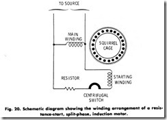
A resistance-start motor is a form of split-phase motor having a resistance connected in series with the starting (sometimes called all.riliai V) winding. A schematic diagram of this type of motor may be represented as in Fig. 20. This shows a resistance connected in series with the starting winding to provide a two-phase rotating-field effect for starting. When the motor reaches approximately 75 percent of its rated speed, a centrifugal switch opens to disconnect the starting winding from the line. This motor is known as resistance-start, split-phase type, and is commonly used on washing machines and similar appliances. It is not practical to build such motors for the heavier types of starting duty.
Split-Capacitor Motors
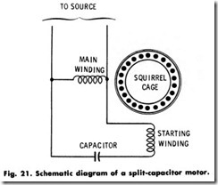
In a split-capacitor motor (Fig. 21), two stationary windings are connected to a single-phase line. The capacitor has the peculiar characteristic of shifting the phase of the current in coil2 with respect to the current in coill. This provides the same action as in the two-phase motor discussed previously, producing the rotating-field effect to rotate
the squirrel-cage rotor. The capacitor is mounted permanently in the circuit. Because capacitors for continuous duty are expensive and somewhat bulky, it is not practical to make this motor for heavy-duty starting.
Capacitor- Start Motors
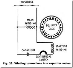
In applications where a high starting torque is required, a motor such as that shown in Fig. 22 is employed. This is only another form of
split-phase motor having a capacitor (or condenser as it was called previously) connected in series with the starting winding . The con struction is similar to the split-capacitor motor, but differs mainly in that the starting winding is disconnected at approximately 75 percent of rated speed by a centrifugal switch, as in the case of the resistance-start motor.
The centrifugal switch is mounted on the motor shaft and, as the name implies, works on the centrifugal principle, disconnecting the starting winding when the speed at which the switch is set is reached. The capacitor-start motor has a greater starting ability than the resis tance-start motor. Because the capacitor is in use only during the starting period, a high capacity can be obtained economically by selecting it for this short-term duty.
Shaded-Pole Motors
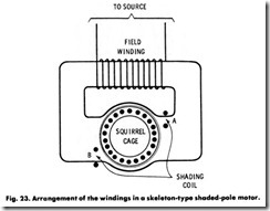
Another type of single-phase induction motor is schematically repre sented in Fig. 23. This motor consists principally of a squirrel-cage rotor and two or more coils with an iron core to increase the magnetic effect. Part of one end of this core is surrounded by a heavy copper loop known as the shading ring. This ring has the characteristic of delaying
the flow of magnetism through it. With alternating current applied to the coil, the magnetism is strong first at A, and then slightly later atB. This gives a rotating-field effect that causes rotation of the squirrel cage in the direction in which the shading ring points. A motor thus constructed is known as a shaded-pole motor.
Because of the limitations of force and current possible in shading poles, it is not feasible to build efficient motors of this type larger than approximately 1/20 hp (or 37.3W). It is used principally on small fans, agitators, and timing devices.
Repulsion-Start Induction Motors
Repulsion-start induction motors are operated in various ways. In the running position, the brushes may or may not be raised. If the same rotor winding is used for both starting and running, the commutator is short circuited at about 75 percent of rated speed to obtain a rotor winding approximating the squirrel cage in its functioning. Other designs have two rotor windings-that is a squirrel cage and a wound winding for running and starting, respectively. In this type, no rotor mechanism is required because the magnetic conditions automatically transfer the burden from one winding to the other as the motor comes up to speed.
Repulsion starting may best be explained by the action of a wire connected to a battery and moved across the face of a magnet. Here, there is a force on the wire which, for example, tends to move it upward or downward, depending on the direction in which the current is flowing. It can thus be demonstrated that a current-carrying wire in a magnetic field has a force acting on it tending to move it in a certain direction. Also, if the direction of the current flowing through the wire is reversed, the force and motion are also reversed.
Repulsion starting operates on this principle. Current is caused to flow in the wires of the rotor winding, and these wires are affected by a magnetic field.
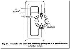
Fig. 24 shows a stationary C-shaped iron core on which is mounted a coil connected to a single-phase supply line. In the opening of the C is a ring of iron on which is wound a continuous and uniform coil. The path of the magnetism produced by the coil wound on the C-shaped core is around through the C-shaped core and, dividing equally, half of the magnetism passes through each half of the iron ring.
The winding and the magnetism are identical in both halves of the ring. Thus, any effect which the magnetism may have on the winding
between E and G will be the same as that produced in windings E and H. This can be proven by connecting an ammeter between points G and H. It will be found that no current is flowing between these tTNo points.
By further tests it can be shown that maximum current will flow when a wire is connected between E and F. Thus, the first requirement of our principle has been satisfied-with a wire connecting E and F, there is a current flowing in the rotor winding.
Assume that the current flows upward in this wire from F to E. At point£, it divides equally, half going to the winding to the left of E, and the other half to the right. Referring to the wires on the outer surface of the ring, those on the right have the current flowing toward the observer, while those on the left have the current flowing away from him. Thus the magnetic field from the C-shaped core tends to force the wires on the right in one direction and those on the left in the other direction. The forces are equal and opposite so that they neutralize each other and no motion takes place.
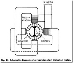
In order for the rotor to rotate, it is necessary to add a magnetic field that can effectively react with the current in the rotor winding. This is done readily by adding another C-shaped core with its own coil, as shown in Fig. 25. The rotor-winding current under each tip of this C-shaped core is all in the same direction, and rotation is obtained. The wire from E to F in Fig. 24 has been replaced with stationary brushes so that a connection is maintained as the rotor turns.
