Electrohydraulic Servo Valves
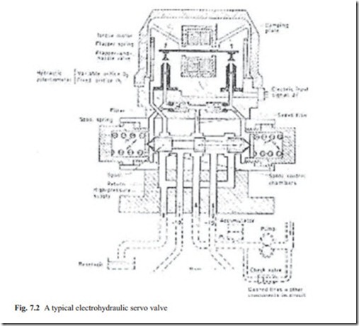
Electrohydraulic valves are devices that change a voltage in the range of milliamp to high pressure oil flow rate. The cross section view of these valves is shown in Fig. 7.2.
Figure 7.2 shows that there are two sections in any servo valve. One section is the magnetic torque configuration and the other section is the spool valve. In the torque motor, there is a magnetic or simple flapper that is connected to two orifices. When the magnetic torque motor is energized, the flapper moves closer to the orifice. This then causes the pressure behind spool to increase and it moves the spool valve. The spool valve is spring loaded at both ends and as a result of a magnetic current the spool moves to a constant position with defined high pressure oil. When
the spool is moved, the high pressure oil flows from one side of the spool to the load which could be a motor. When the direction of magnetic field is reversed, the spool moves in the opposite direction. This closes one side of the outlet port and the other port opens allowing that the high pressure oil flows in the other outlet port. The oil eventually returns to the reservoir and is pumped again.
The reader must know that there are various types of servo valves but the principle of operation is the same as was explained above. Some may have internal feedback in the spool valve instead of the spring. The important dynamic behavior of servo valve must be provided by manufacturers. This could be in the form of the frequency response of servo valves or could be in the form of a step input response. From the response, an approximate transfer function can be obtained. The important points of operation are in low frequency range because at high frequency, the valve just cannot respond because of the masses of spool valve.
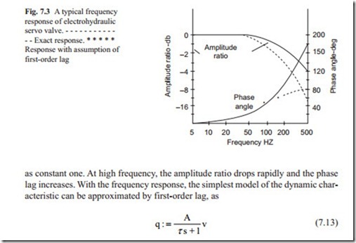
A typical frequency response of a typical servo valve is shown in Fig. 7.3.
The frequency response shown in Fig. 7.3 is in non-dimensionalized form. It shows that at low frequency the phase lag is small and the amplitude ratio remains
In Eq. (7.13), A is constant of proportionality and τ is the time constant. The parameter ( A) can be obtained by knowing the flow rate for a given voltage supplied to the torque motor. The time constant may be approximately obtained from the frequency response. All the parameters must be given by manufacturers. The frequency re- sponse shows that at high frequency the phase lag goes above 90° indicating that a better model would be a second-order transfer function. Because the response of hydraulic servo motors is much slower than the servo valve the above model gives an accurate model for the servo valve. In some very high performance applications, a second-order transfer function is more accurate. The parameters of the transfer function, that is, natural frequency, damping ratio, and the gain must be identified from the frequency response or step input response. The manufacturers must pro- vide the frequency response or step input response. By referring to the characteristic behavior of a second-order transfer function, the above mentioned parameters may be obtained.
There are some well known identification techniques that may be used but these methods are beyond the scope of this book.

