RETROFITTING INHERENT SENSORS
FORD Motor Co., one of the nation’s largest users of integral-horse power motors, has long felt the need for a motor protection method that would keep overloaded motors on the line as long as possible and which could be reset by the operator without calling an electrician. A pioneer ap plication of inherent temperature sensors was made at Ford’s Dearborn plant. It was on a 3-hp, 3-phase, 460- volt motor that had a long history of burnout problems.
Small barium-titanate sensors were attached to the end-turn windings of each of the three phases and con nected in series with a relay module. This first unit fully protected the mo tor under severe locked-rotor condi tions amounting to several thousand overload cycles. During the test, the leads were shorted together period ically to evaluate the fail-safe feature of the system under such a condition. In all instances, the motor was shut down when either an overtemperature or a short-circuit condition oc curred. Following this, several other troublesome motors were modified to use inherent protection. In all cases, the problem was solved.This was the start of a new busi ness for apparatus service firms in the Detroit area. Following are obser vations of two such shops, Jay Elec tric and A & C Electric, on their expe riences with the new form of protec tion.
Jay Electric
Jay Electric began implanting tem perature sensors in motors for Ford Motor Co. plants in the Detroit area about four years ago. At that time it was almost on a developmental basis, and the customer was keeping close tabs on each motor’s performance af ter it went back into service. How ever, no motor protected by the new system has yet been returned for fur ther repair, and for the past several months virtually every rewind job for Ford has been accompanied by an or der f or the sensors.
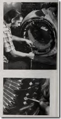
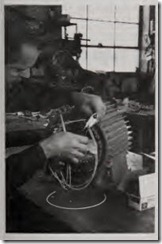
AI Leach of Jay Electric reports that installation is easy when it’s don e at the time of rewinding, adding only 15 or 20 minutes to the job. The sen sors are positioned in the end turn s of one \Vinding from each phase so th at th ey are surrounded by wind ings.
Jay’s practice is to place the sensors aroun d the circumference of the sta tor win dings approximately 120 deg apart . This is more difficult than plac ing th em on adjacent phase coils, be cause the repairman must count the coils a roun d the circumference care f ull y to make sure that one sensor is o n each ph ase. H owe,·er, Jay’s me th od giYes better protection again st the effect of a local external heat source wh ich could raise the tem peratur e of one part of a motor more t han the rem ain der. (This could hap pen, for exampl e, to a motor mounted on a furnace or next to uninsulated hot pipes.)
Jay feels t hat the ideal place to sense true w in ding temperature is abou t halfw ay between the insulation spaces and h alf way between the nose of the bundl e an d the end of the stator slot. A sensor placed too close to the nose of the coil will sense a lower temperature than the rest of the coil, since it comes into contact with more cooling air. Placed too close to the slot, it may pick up heat from the laminations or housing, which won’t necessarily represent winding tem perature.
So far, all motors that haYe been retrofitted at Jay have been the stan dard form-wound type, but experi ments with other types of motors in dicate that other types of windings will not create any problems.
A & C Electric
lost of the sen·ice work done by A & C Electric l\lotor Repair Co. is for plants of the big-three ·automobile companies, but they also do work for suppliers to the automotiYe industry.
A & C began doing implants of sensors for local plants of Ford 1Iotor Co. about two years ago. They found that it takes from 30 to 45 minutes to con Yert a motor from scratch, including dismantling. sensor-mounting and wiring, and reassembly. If the motor is already disassembled, the retro fitting takes only about 15 minutes.
If these sensors eliminate motor burnouts, isn’t A & C worried about a falling off of their rewind business? Not at all, they say. After all, there are about two million motors in the Detroit area, and they fail for many reasons other than burned-out wind ings. Also, the fact that users will tend to push sensor-equipped motors to the limit of their overload capabil ity may mean that other component failures may show up in increasing numbers.
The company finds that, for the customer, the cost of retrofitting pro tection is such that the installation generally pays only where the motor is used in a critica l process, is likely to be oYerloaded, and is on a machine where replacement is time-consum i ng and downtime is expensiYe. Inter est outside the automotive industry is picking up slowly, but A & C belieYes it may be quite some time before the units are really widely used through out industry.
A & C has some suggestions for other shops thinking of offering this new sen·ice to customers.
1. Make sure you protect eYery phase in the motor.
2. Placement of the sensor 12 in. one way or another won’t make any difference, but it should be placed ap proximately in the center (side to side) of the phase coil and not too close to the insulation between coils. (The insulation could affect the tem perature the sensor “sees.”)
3. Don’t place the sensors at the end of the motor where the stator power leads are connected to the windings.
4. Make sure that the leads inter connecting the sensors are firmly tied down to aYoid contact with other parts of the motor.
5. Make sure each sensor is in intimate contact with the windings. We make an effort to place the sensor in a creYice in the windings. While there is no e,·idence that this is essential to proper performance, all the motors we haYe retrofitted appear to be working well. A crevice provides more surface contact area with the sensor tip, which should enable the system to more closely track the actual winding temperature.
6. Use only the epoxy material for securing the sensors in place that is proYided by the manufacturer of the retrofit kit. This epoxy has a ,·ery high heat-transfer coefficient. In one case when we were pushed to get a motor out the door, we didn’t haYe the right epoxy, so we used a standard formulation we had around the shop. When we tested the motor. the sensor system did not work efficiently and we had to remo,·e the sensors and wait for the proper epoxy.
7. lake sure you use the sensor specified for the motor temperature rating. One customer was so anxious for his motor that he gave us the go ahead to use a sensor for a Class B motor (which was all we had on hand at the moment) on his Class F motor. The Class B sensor is calibrated to kick out at 135F. We got the motor right back from the customer because the sensor kept doing its job, and of course the Class F motor wasn’t working at anywhere near its burn out point. You can’t fool these sen sors.

