SERIES 60 TWO-POSITION CONTROL CIRCUITS
APPLICATION
A Series 60 two-position control circuit is a line- or low- voltage circuit which requires a single-pole, double-throw controller to operate a reversible drive actuator. Series 60 two- position control circuits can be used for open-closed control of valves or dampers.
The basic Series 60 circuit contains a Series 60 actuator and a Series 60 controller. Limit controllers can be added where required.
EQUIPMENT
CONTROLLERS
1. Temperature controllers.
2. Humidity controllers.
3. Pressure controllers.
4. Any single-pole, double-throw controller such as a relay or switch.
Series 60 two-position controllers are line-voltage rated devices and have a spdt switching action that is obtained by use of a mercury switch or snap-acting contacts. Series 60 controllers can operate line- or low-voltage devices.
ACTUATORS
Series 60 actuators consist of a low-voltage, reversible motor which operates a gear train to rotate a drive shaft. The actuator drives open and closed by switching voltage input to the motor, not depending on a spring to close. Built-in limit switches stop the motor at open and closed positions of the actuator stroke. The drive shaft is mechanically connected to the damper or valve by a suitable linkage. On power interruption or loss of control signal, the actuator maintains its current position between limits. This allows the actuator to be used in either two-position applications or floating applications (see SERIES 60 FLOATING CONTROL CIRCUITS).
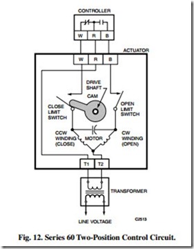
Most Series 60 actuators have low-voltage motors. Line- voltage models will often have a built-in transformer to change the incoming line voltage to low voltage for the control circuit and the motor. Low-voltage models require an external transformer to supply voltage to the actuator. See Figure 12. Some Series 60 actuators have line-voltage motors.
Low-voltage controllers cannot be used on line-voltage control circuits. If the control circuit is low voltage, it can use either a line-voltage controller or any low-voltage, spdt, or floating controller.
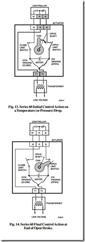
Figure 12 illustrates the actuator in the closed position. On a drop in temperature or pressure, the controller contacts close R to B and open R to W (Fig. 13). The OPEN winding is energized and the actuator shaft rotates cw until it reaches the limit of travel and opens the OPEN limit switch (Fig. 14). The actuator remains in this position until a rise in temperature or pressure causes the controller contacts R to B to open and R to W to close. The CLOSE coil is then energized and the actuator shaft rotates ccw until it reaches the limit of travel and opens the CLOSE limit switch.
NOTE: Most Honeywell Series 60 controllers close R to B on a fall in the controlled variable and R to W on a rise.
CONTROL COMBINATIONS
The following are representative Series 60 two-position control circuits. Notice that many of these functions can be done with Series 40 or 80 systems. If spring-return action is required when power fails, use Series 40 or 80.
TWO-POSITION CONTROL OF STEAM VALVE
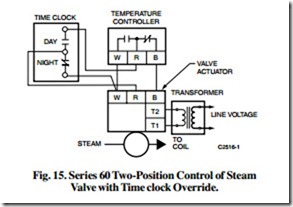
Figure 15 illustrates two-position control of a steam valve. During the day when the temperature sensed by the Series 60 controller drops below the setpoint, contacts R to B close and the actuator opens the valve allowing the steam to flow to the coil. On a rise in temperature, contacts R to W close and the actuator closes the valve stopping the flow of steam. At night the time clock overrides the temperature controller and drives the actuator/valve closed.
SUMMER/WINTER CHANGEOVER CONTROL OF A THREE-WAY DIVERTING VALVE
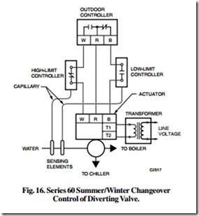
Figure 16 illustrates summer/winter changeover control of a three-way diverting valve. A Series 60 controller senses outdoor air temperature to determine when to change over from heating to cooling. When the outdoor air temperature drops below the setpoint of the controller, contacts R to W open and R to B close calling for winter operation. The low- limit controller, located in the return water line, senses the return- water temperature. If the water temperature is above the setpoint of the low limit controller, the R to B circuit completes, and the actuator positions the diverting valve to send the return water to the boiler. If the low-limit controller senses that the return water is too cool, the contacts open, and the valve remains in a position to divert the return water through the chiller. This circuit protects the boiler from thermal shock by not allowing chilled water into the hot boiler.
When the outdoor air temperature rises above the setpoint of the controller, contacts R to B open and R to W close calling for summer operation. If the water temperature is below the setting of the high limit, the R to W circuit completes, and the actuator positions the diverting valve to send the return water to the chiller. If the high-limit controller senses that the return water is too warm, the contacts open, and the valve remains in a position to divert the return water through the boiler. This circuit protects the chiller by not allowing hot water into the chiller.
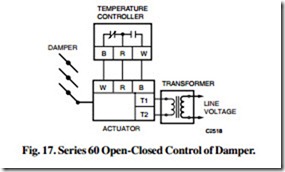
Figure 17 illustrates open-closed control of a damper. A Series 60 actuator is linked to a ventilating damper. When the controller senses that the temperature in the interior of the building is above the controller setpoint, contacts R to B open and R to W close. This powers the R to B actuator terminals causing the actuator shaft to turn, opening the dampers. When the controller senses that the temperature is below the setpoint, contacts R to W open and R to B close causing the actuator shaft to close the damper.
