How to locate, test, and repair
After determining what the symptom of the electronic product is, you must locate the section that has the defective part before you can remove and replace that part. With a horizontal white line in a TV chassis, representing no vertical sweep, the defective component is found in the vertical section of the chassis. When the raster and picture are pulled in on the sides, you know the trouble lies in the horizontal output stages or in sufficient voltage applied to the horizontal section from the low-voltage power supply.
lf the TV chassis is dead and will not start up, check for an open fuse, badly soldered driver transformer, and problems within the low-voltage power supply. After determining what the symptom is, go directly to that section and 1nake voltage, waveform, and component tests.
Remember, you don’t have a schematic diagram to locate the suspected component with accurate voltage measurements. Make voltage, resistance, scope, continuity, and semiconductor tests to determine if a part is defective.
With only a DMM
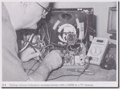
One of the most useful test instruments in electronics servicing is the digital multi meter (DMM). The DMM can be used to make critical voltage, resistance, and current tests. The deluxe DMM can be used to test capacitors, diodes, and transistors. Besides checking out fixed diodes, the DMM diode test can be used quickly and efficiently to test each transistor right in the circuit. The DMM can determine the real low resistance of transistor bias resistors under 1 ohm. Besides taking critical de voltages, the DMM can make accurate ac voltage measurements . Some DMMs also can check frequency, inductance, and capacity (Fig. 2-1).
Correct electronic test equipment
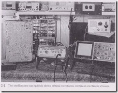
Besides the DMM, the oscilloscope is one of the most used inst1uments to test for correct waveforms on the service bench. You can easily locate a defective component with critical waveforms in many different consumer electronics products. A dual-trace oscillscope is needed with at least a 35- or 40-MHz frequency bandwidth (higher in some cases). Knowing how to use the scope will save a lot of time on the service bench. Don’t let the scope sit idle; use it. Besides regular hand tools, special and additional test equipment is listed in each chapter.
REQUIRED TEST EQUIPMENT FOR TV SERVICING
1. DMM
2. Oscilloscope (Fig. 2-2)
3. Semiconductor tester
4. Equivalent series resistance (ESR) meter
5. Audio signal generator
6. Sweep generator
7. Color-dot-bar generator
8. Radiofrequency (RF) signal generator
9. Frequency counter
10. Capacitance meter
11. Cathode-ray tube (CRT) tester and rejuvenator
12. High-voltage probe
13. Isolation transformer
14. Soldering station
15. Desoldering station
REQUIRED TEST EQUIPMENT FOR RADIOS AND CASSETTE PLAYERS
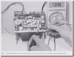
1. DMM (Fig. 2-3)
2. Volt-ohm-milliammeter (VOM)
3. Semiconductor tester
4. ESR meter
5. Signal tracer
6. Signal generator
7. Frequency counter
8. Test cassettes (1, 3, 10kHz)
9. Soldering station
10. Isolation transformer
11. De power supply
REQUIRED TEST EQUIPMENT FOR CD PLAYER TROUBLESHOOTING
1. DMM
2. Semiconductor tester
3. ESR meter
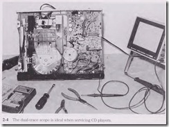
4. Dual-trace oscilloscope (Fig. 2-4)
5. Optical power meter
6. Low-frequency audio frequency (AF) oscillator
7. Signal generator
8. Frequency counter
9. Test discs
10. Several special tools, manufacturers’ jigs, wrist straps, etc.
11. Variable isolation transformer
REQUIRED TEST EQUIPMENT FOR VCR REPAIR
1. DMM
2. National Television System Committee (NTSC) pattern
3. Ac millivoltmeter (RMS)
4. Frequency counter
5. De power supply
6. Oscilloscope
7. Isolation transformer
8. Alignment table
9. Blank tape
10. Special manufacturers’ jigs
11. Soldering station
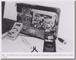
12. ESR meter (Fig. 2-5)
Who’s on first?
What is the first thing you should do? What is the symptom? You must know how the unit is acting up before troubleshooting the chassis. For instance, a dead TV might be caused by an open fuse, the low-voltage power supply, or the horizontal output circuits. A white line on the raster of a portable TV indicates a problem of insufficient Sweep in the vertical section. Sides pulled in on the raster might indicate a defective low-voltage power supply, horizontal sweep, or pincushion circuits.
A dead symptom in stereo radio circuits might indicate a defective low-voltage power supply to the audio output transistor, integrated circuit (IC), or speaker. Excessive hum within a large stereo amplifier might be caused by defective filter capacitors. Pickup hum might point to worn input cables or circuits. No rotation of the disc in a CD player might be caused by a bad spindle motor or drive circuits. Use all the symptoms to locate the defective section within the electronic product.
Case histories
Keeping track of what occurs, such as an unusual symptom or a “tough dog,” can help the next time around. A case history on a certain electronic product can help on an other chassis with the same symptom. Case histories should be looked at after determining what section the symptoms point to. Keep all cases iJ1 a card file, on computer, or right on the schematic. Remember, the case history of one unit may help to solve problems in other chassis. Don’t forget to write down or otherwise record all “tough dog” case histories.
A COMMON TV CASE HISTORY
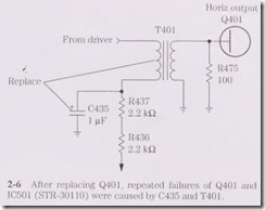
An erratic or intermittent startup symptom with chassis shutdown in a TV chassis can be caused by poorly soldered joints on the horizontal driver transformer. Resolder all terminals on the driver transformer the first thing with no startup, intermittent startup, and shutdown problems. This same symptom occurs in just about every TV chassis (Fig. 2-6).
After replacing the horizontal output transistor for a dead sympto1n and the out put transistor becomes shorted once again, solder up all terminals of the driver trans former. Check the resistance of the voltage resistor feeding the primary winding of the driver transformer. Replace the bypass or electrolytic capacitor at the transformer voltage resistor.
Suspect a defective flyback or poorly soldered co1u1ection on the horizontal output transformer. Scope for insufficient horizontal drive signal at the base terminal of the output transistor. Last but not least, check for a defective safety capacitor. Most of these service problems can happen in any TV chassis.
A COMMON RADIO-CASSETTE CASE HISTORY
Speed problems within the cassette player occur at one time or another in virtually all radio-cassette players. A stretched rubber drive belt or oil on the belt can cause improper speed. Worn rubber tires on the idler wheel can cause slow or erratic speed. A dry or worn spindle flywheel can cause improper speed. Check cassette speed problems with a test cassette (1 kHz) and a frequency counter to determine the correct speed.
A COMMON VCR CASE HISTORY
A defective capstan motor can cause many different proble1ns within a VCR. A bad capstan motor or a frozen capstan bearing can cause erratic motor speed problems. A defective capstan motor with a flat shaft may not start up the next time. The bad capstan motor can develop slow speed rotation. A defective capstan motor also might cause improper or no fast-forward or rewind or shutdown problems. Just keep track of the un usual Symptoms that can result from a defective capstan motor and write them down on the schematic.
Isolation
Look the chassis over for burned, damaged, or cracked components within the section that possibly can be the cause of the Symptom . Inspect critical traces or printed circuit (PC) wiring on the bottom side of the chassis for overheated terminals and badly soldered spots. Usually a large blob of solder can cover up a poorly soldered terminal from a resistor or capacitor. Overheated parts can be isolated by touch. Touching the chassis and parts can indicate the intermittent component.
After isolating the potentially defective section, isolate the defective part with transistor, IC, resistance, scope, and continuity tests. Test the transistors in or out of the circuit with a transistor-diode test using a DMM or a beta transistor tester. Check all suspected ICs with signal in and out, voltage, and resistance measurements. Be fore you can pinpoint the defective part, you must locate it on the chassis without a schematic.
Location, location
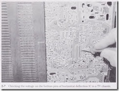
After isolating the various Symptoms, find the correct section in which the trouble might occur . Look for large components such as filter capacitors for the low-voltage power source, transistors mounted on separate heat sinks inside the chassis for vertical output transistors or ICs, and horizontal output transistors on separate heat sinks or metal chassis for the horizontal output circuits (Fig. 2-7).
Another method for determining if you are in the correct section is to take the numbers located on the transistors and IC components and look them up in a semiconductor replacement manual. The manual tells you what pin goes where and what circuit. it ties into on the chassis.
Look at the outline drawing for the correct pin connections. For instance, part number AN5435 lists as a color deflection signal processor IC in the RCA series replacement manual. The universal replacement is an SK9299 IC with pin 15as the supply voltage pin (Vcc). The horizontal drive output is pin 6, and the vertical output is pin 9. Also, the SK9299 has a total of 18 pins. Double-check with the IC mounted on the chassis for the correct number of pins, the right section, and the correct universal replacement.
Let’s say you have a Panasonic portable TV that comes in without a model number. The model number has been torn off, but it looks like a fairly new set, one that you have never worked on before. The symptom is a tic-tic sound with B+ present at the horizontal output transistor and no high voltage.
By supplying a horizontal pulse at the horizontal driver, you make the set run, indicating that the horizontal output stages and high-voltage and flyback circuits are normal . You think that the AN5435 IC is the horizontal/vertical cow1tdown IC. But what pin is the voltage source (Vcc)? You look it up in the semiconductor replacement manual.
The AN5435 IC is a color TV deflection signal processor and can be replaced with an RCA SK9299 IC. Now you have located the correct IC and section where the trouble is. · Before replacing the IC, take voltage measurements on all the IC pins. Usually the highest voltage is the supply pin (Vcc). Supply voltage to the deflection IC is usually from 10 to 25 V. In this case all pins are low in voltage. So you check the highest- voltage pin and trace it back to the low-voltage source. If the low-voltage source is supplied through flyback derived secondary sources, you are out of luck. Look up the supply voltage pin on the out line drawing of the replacement SK9299 IC. Pin 6 ties to the supply voltage source.
Inject an external10 or 12 Vat pin 6 with the scope probe on the horizontal driver (pin 15). If the horizontal waveform is normal, the IC is good. Double-check the vertical output drive waveform at pin 9. If there is no waveform at either pin, suspect a defective IC or leaky components tied to the IC pins and common ground. Replace the IC with a universal replacement if the original part number is not available. Sometimes the IC’s voltage and resistance measurements are normal, but there are still no waveforms. Replace the IC at once.
Check the voltage at pin 6. Low or no voltage can indicate a leaky IC, improper sup ply voltage, or no voltage from the flyback secondary source. Trace the PC board wiring back to the supply source to locate a defective isolation resistor, silicon diode, or small electrolytic capacitor. By simply checking the number on the IC or transistor you can determine the section where the trouble is located, the correct pin, and the total number of pins.
