Connections to switches
Connections to switches may be made by soldering, welding, crimping, screw fastening or by various connectors or other plug-in fittings. The use of soldering is now comparatively rare, because unless the switch is mounted on a PCB which can be dip-soldered this will require manual assembly at this point. Velded connections are used where robot welders are employed for other connection work, or where military assembly standards insist on the greater reliability of welding. By far the most common connection method for panel switches (as distinct from PCB- mounted switches) is crimping, because this is very much better adapted for production use. Vhere printed circuit boards are prepared with leads for fitting into various housings, the leads will often be fitted with bullet or blade crimped-on connectors so that switch connections can be made. This assumes the use of switches with suitable terminations, and the most common switch termination of this type is the flat blade, so the connecting cable should carry a matching receptacle. Piggyback receptacles can be used when wiring has to be carried from one switch to another.
Non-contact switching
Low-voltage switching can be carried out by semiconductor devices, notably FETs, with no mechanically moving contacts. The use of devices such as FETs and thyristors is more correctly classed as a type of relay
action, however, since the switching is in response to an electrical signal. The use of the Hall effect is a true contactless switching effect, because a non-electrical input (the movement of a magnet or a change in a magnetic field) causes a current path to be made or broken. Switching of this type is now very common, notably in the contact-breaker mechanisms of car ignition circuits that use semiconductor switching methods.
Contactless switching has a number of advantages, particularly in hazardous environments. The switching action does not depend on any form of mechanical action, so that problems of rusting, jamming, wear and fatigue no longer exist. Since the ‘contacts’ are internal to the semiconductor’s material they are not liable to corrosion, particularly if the whole switch is encapsulated. Low voltages and currents can be used, avoiding spark risks even if wires are damaged. The switching action can be very fast and in many cases can have variable sensitivity.
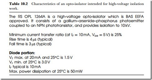
The main drawback of contactless switches is that the action generally requires low-voltage DC at some point – I am excluding the action of thyristors and Triacs here. The control action of the switch may, however, need to make or break circuits that operate at higher voltages, and this requires some form of relay action. The conventional contact form of relay can always be used, and in some applications may be required by regulations, but the alternative is a contactless form of relay, the opto-isolator. The opto-isolator is shown in outline in Figure 10.5. It consists of an LED whose light can be focused onto a photocell, with no electrical contact between the LED and the photocell. Vhen the LED is illuminated, the light path to the photocell ensures that there will be an output from the photocell, and this can be amplified and used for switching purposes. The devices are encapsulated to ensure that all the light from the LED will reach the photocell, and no ambient light can reach the photocell. Table 10.2 shows some typical opto-isolator characteristics.
Since the LEDcan be part of a low-voltage circuit, and the photocell can be part of a circuit that is connected to mains or other high-voltage supplies, the opto-isolator can be a very useful linking device. One particular advantage is that the opto-isolator action can be fast, allowing switching at audio and even video frequencies. It is therefore a unique way
of transmitting a signal which may contain both high frequencies and DC levels between two very different voltage levels. The most obvious use is to link a low-voltage circuit, such as a touchpad, to a high-voltage circuit, such as a thyristor controller, but this use is often prohibited by wiring regulations, so that some care has to be taken when specifying the use of optoisolators. Since thyristors can be triggered by pulses applied via transformers, this alternative is more commonly used.

