The Input
For the user, “the input” is often just a socket—often one groped for amidst a tangle of leads. This chapter untangles the details of the rarely recounted considerations that lie behind audio power amplifier input sockets that enable the signal source to connect to the amplifier (and maybe to many amps) with the least loss of fidelity and without introducing unwanted noise.
The amplifier is treated as a whole without considering the power capability or type of the output section.
Input Sensitivity and Gain Requirements
Definition
Input sensitivity is the signal level at the input needed to drive an amplifier up to its full capability, to just before clip, into a stated, nominal impedance, often 8 ohms. Clip may be defined as the onset of visible waveform flattening or as a certain percentage THD+N distortion factor.
An older, less used definition (favored in the 1978 IHF standard) is the signal level needed to deliver I watt into a given nominal load, say 8f2. This is fine for comparing or normalizing drive levels between amps having different power ratings, but as input sensitivity per se has no particular merit, the usefulness, for real amplifiers and speakers of widely varying power capabilities and sensitivities, ends there.
Description
Sensitivity is usually expressed as a voltage, either directly in volts or millivolts (1/1000ths of a volt), or in dBu. Mostly, sensitivity figures are assumed to be rms values (cf. peak) and also specified with a steady sine wave, and for power amps in particular, with loading—all unless stated otherwise. If a peak (or any other non-rms) voltage value is cited, the maximum output to which it is referred must also be cited likewise, so like is being compared with like.
Variables
The sensitivity of an amplifier depends (as defined earlier) on gain and swing. If an amp’s output power rating, hence voltage swing capability into a given load impedance, were increased, maintaining the sensitivity requires more gain from the amplifier. This is a consideration for the maker and the installer who uses different sizes of a given design.
Do-It-Yourself Gain Resetting
For those uses with two or more different models and/or makes of amplifier, it is likely that sensitivities (however referred) will differ. Gain controls may not be present or it may be desired not to use them. If so, to align the system (ideally within a fraction of a dB), all the amps enter clip at about the same drive level and the gain(s) of one type of amp will need changing. Usually, any gain controls are assumed to be at maximum. Then any “accidental adjustments” can only cause reduced, not excess, gain.
In most well-designed, conventional high NFB power amps, gain may be changed up or down easily by changing one (global feedback) resistor per channel. The part being changed is usually in the output section. Changing gain by up to +10 dB or down by as much as –6 dB should have relatively little effect on sonic quality, assuming that RF stability is not upset. However, noise will be altered pro-rata.
In low- and zero-feedback designs, the availability of gain changing is far less, and the effect on both measured and sonic performances of even a modest 10-dB (X3) adjustment will be far more marked.
Gain Restriction
In some power amp designs, gain changes may be unavailable because they would upset RF stability, imperil a finally balanced gain/feedback structure, or violate some arbitrary %THD+N limit or other basic performance indication. Thus amplifiers from a product family spanning a range of output power ratings may have very similar gains (+ to –3 dB); thus sensitivities (mV, V) almost commensurate with their ascending voltage swing. The upshot of this approach is (for example) a 2-kW 8fΩ amplifier, which only provides 100 W at normal drive levels (0 dBu say). The +13-dBu/3.5-V rms input drive needed for full output makes it safer and more likely that the high swing will be kept in reserve as an inviolate headroom.
In other words, in lieu of increased gain when output swing is increased, such an amplifier will need to be driven harder, that is, rated less sensitive. If the headroom achieved is ever used, then the higher input drive levels can cause increased distortion in the input stage. This effect will be noted most in esoteric amps with low feedback, but is still there in conventional high NFB amps.
Gain and Fidelity
As noted, the positive side of having high swing amplifiers desensitized, by not increasing gain commensurate with the increased voltage swing is that headroom occurs by default if the system’s level/gain settings are not then altered. Reduced gain also reduces the risk of speaker damage by accidental loud blasts, dropped mics, styli, etc. Also, the audibility of the system’s residual noise is lowered.
CM Stress
In conventional power amplifiers with high NFB, “common mode distortion,” measurable as %THD+ N,1 occurs because of common-mode voltage stress on the input stage, whether differential or single ended, with the latter suffering CM stress if, as is common, it is noninverting. The threshold voltage, ‘Vth’—above which the input voltage to such an op-amp-type input becomes highly nonlinear when open loop may be sonically significant.2,3 These setbacks may not be revealed with conventional tests, notably
%THD+N, which can contrarily show lowered distortion at high input drive test levels, because the noise (+N) may “out-reduce” the rising common mode distortion.1
Real Figures
The sensitivity of every amplifier needs to match the zero (normal) levels of sources it is intended to be driven by. These vary. The upshot of all the factors is a spread of amplifier sensitivities that users know all too well (Table 8.1).
Ideally, there could be just one input sensitivity for all these uses. One that most could accept is the de facto professional standard of 0-dBu alias 775 mV. As a general rule, most lightweight domestic hi-fi and home studio equipment is likely to be more sensitive than 0 dBu, with pro equipment likewise less sensitive.
However, as just discussed, a specific lower value, as low as 30 mV, may be best (at least in high NFB circuits) from the viewpoint of circuit and device physics for absolute best linearity.2 However, the higher voltages that are mostly needed by desensitized high swing amplifiers (e.g., driving 2 V or +SdBu and above to clip) confer the highest SNR, hence dynamic range, and also the highest RF EMI and CMV immunity. So the best of both these worlds appears not to be immediately reconcilable.
As most amplifiers are not pure voltage sources, when driven with continuous, high- level test signals into a real (or simulated) loudspeaker load (as opposed to an ideal, simple resistive load), the sensitivity (for a given clip level) can appear to increase at some frequencies, as the maximum output voltage with a conventional amplifier having an unregulated supply is reduced by typically by –0.5 to –2 dB. The average shortfall is likely to be less with program, at least at mid- and high frequencies. It follows that there is a complex frequency-conscious and dynamic peak-to-mean disparity in practical amplifiers’ sensitivity ratings. The purer the voltage source, the less this can happen.
Gain and Swing
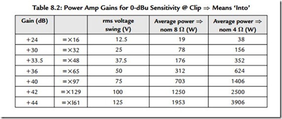
Table 8.2 shows the gain requirements both in dB for some “round-figured” voltage swings, and how the nominal power then varies into 4 and 8 ohms.
For other sensitivities, gains are determined easily by appropriate subtraction or addition, for example, for +4 dBu, subtract 4 dB from the indicated gain(s) and for –10 dBu, add 10 dB to the indicated gain(s).
Input Impedance (Zin)
Introduction
The amplifier’s input impedance is the loading presented by the amplifier to the signal source driving (or “looking up” or “into”) it.
Impedances (often abbreviated ‘z’) are rated in ohms (Ω). As in this case, ohmic values are nearly always over 1000; the counting is usually in thousands (k). 10 k or 10 kΩ (“10 k ohm”) is easier to say than “ten thousand ohms.” When near a million or over, ‘M’ for ‘Mega’ is used, for example, 1 MΩ is 1000 kΩ.
Common Values
With ordinary, high NFB power amplifiers, high input impedances (high Zin, say above 10 kΩ), to 1 MΩ or more, are readily attained. For most sources, this is analogous to
very light loading. However, in most cases, power amp input impedances are commonly at the low end of this range, at between 10 and 22 kΩ. This restricts noise and buzzes when (particularly unbalanced) inputs are left open, unused, or floating, especially when cables are unplugged at the source end. This is less of a problem with short cables and in domestic environments.
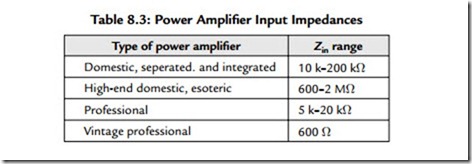
The nominal values of amplifier input impedances vary widely. As a rule, professional equipment is defined in Table 8.3.
If balanced, Zin is the differential mode Z.
The input impedance of equipment may be described as the source’s load impedance. This is true enough at frequencies below l kHz. However, load impedance (since the signal source may be across a room, 100 yards down a hall, or even half-way across a field) is the totality of loading, namely including all the cable capacitance, which takes effect increasingly above 3 kHz.
Audio is Not RF
Precise “impedance matching,” where specific impedances (often 50 or 75 ohms) must be adhered to, is correct for radio frequencies, where cables above a meter or so act as a transmission line.4 But at the highest audible frequencies (20 kHz) even a 200-m-long input cable in a stadium PA system doesn’t behave as a transmission line.
Where the wavelength (the dual of frequency) is a fair fraction, say 20 or 10 times greater than the cable, cables look mainly like the respective sums of their resistance, capacitance, and inductance. As the ratio falls, the cable begins to behave increasingly like a transmission line.
Voltage Matching
Since the widespread use of NFB (50 years ago), the majority of power amplifiers’ inputs have been voltage matched. This means that the source impedance is low—much lower (at least 10 times less) than the total destination, or load impedance.5,6 The intention is
to transfer the signal, which is encoded as a voltage “wiggle,” without significant loss of headroom, dynamic range, or detailing.
The source’s impedance—whatever’s feeding the amplifier(s)—also has to be low enough and remain so at hf to support a fiat hf response into the capacitative loading of likely cable lengths. Voltage matching is defined by de facto industry practice, in the IEC.268
standard. Here, recommended input impedances are 10 kΩ or over and equipment source
impedances are 50 Ω or less. This is easily memorized as
With voltage matching there is no sharply defined “right” impedance. Except that in high common mode rejection (CMR) balanced systems and high resolution stereo systems
alike, an amplifier’s individual input impedances may be ultra-matched. Since with
voltage matched systems, the wanted input signal is a voltage, the ideal, “noninvasive” amplifier input or load impedance would appear to be very high, say 1 MΩ. Then only minuscule current would be taken from the source.
High Impedances
Some high-end hi-fi makers have taken the high impedance route, claiming better sonics. This may be inseparable from the circuitry used to create the high-Z conditions, and not necessarily down to the high-Z conditions per se.
In power amps with low (or zero) feedback, and using bipolar junction transistors (BJTs) in the input section, high input impedances (above 10 kΩ) can be more difficult to implement consistently. On this basis, the early transistor amplifiers sometimes had their inputs rated in μA of input current drawn! In contrast, there is usually no difficulty attaining impedances as high as 1 MΩ or more, when the input stage parts are valves, JFET or insulated gate FET (MOSFET) or any combination of these—whether loop or local feedback is zero, low, or high.
When unterminated, such high impedance circuits are noisier (hissier) and far more liable to allow parts to be microphonic than lower (“normal”) impedance ones.7 Demonstration is simple enough: try tapping the appropriate capacitors with an insulated tool while listening with full-range speaker(s) connected. High impedance inputs can also be the cause of difficulties and compromises with direct coupling. However, unless the input is direct coupled, or is at least coupled via very large capacitors, LF and subsonic microphony and electrostatic noise pick-up will not “see” the lower source impedance and will persist in accordance with the high impedance.
Low Impedances
As input impedance is lowered, there is less microphony and electrostatic noise pick- up when the amplifier inputs are disconnected, even with unshielded cabling. However, loading is increased, as is ultimately the susceptibility to magnetic field noise pick-up, which is much, much harder to shield against.
Loading
A single load of (say) l kfΩ may or may not compromise the source’s performance. But two or a few of such loads almost certainly will, unless the source is rated appropriately
(see later). Low impedance inputs are also the most easily damaged if one amp’s output
is accidentally connected to another’s input. Added protection would add complexity, increase the cost, and likely degrade sonics.
In Tandem
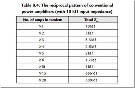
In professional (and even a few domestic) applications it is normal for each signal source to drive more than one amplifier input. The loading of amplifiers driven in tandem is cumulative: each added amplifier reduces the impedance (or increases the loading) pro- rata in accordance with its impedance. Assuming conventional power amplifiers with
10 kf2 input impedance, the reciprocal pattern is shown in Table 8.4.
Note that there are very few types and models of the likely sources (e.g., active crossovers, delay lines, preamps) that are rated and able to drive impedances of below 600 ohms without degraded performance. Much pro-gear is rated and even specified for 600 ohms, but still gives its best measured and sonic performance into 2 k or even higher.
For large tandem systems, existing equipment usually has to be retro-fitted with special line-driver amplifiers, or these are added as independent units, in line. Line drivers used in live sound practice do not expand the allowable loading by much, usually down to 300 ohms and possibly as low as 75 ohms. To be sure, only 50% of this rating would
be used. The rest allows for tolerances, variables (see later), add ons, and the cable’s capacitance loading at hf. In a major concert where 100 or more power amps have been
required to handle just one frequency band alone,8 the signal was split among up to 10 line drivers, all daisy chained off 1 line driver. This method is far preferable to having multiple crossovers, which might superficially simplify the signal path, but would also introduce near impossible set-up and band-matching demands.
Multiconnection
When one signal has to feed many amplifiers, it is normal to connect the amplifiers by daisy chaining. To permit this, amplifiers made for professional use have both female (input) and also male (output) XLR (or other, gendered or ungendered in/out) connectors, linked together in parallel. “Daisy chaining” means physically, as the name suggests,
that a short cable “tail” carrying the input signal loops from one amplifier to the next in the rack or array. The signal being passed on is not really entering each amplifiers’
input stage, but merely using the input sockets and case-work as a durable and shielded Y-splitting node. An alternative would be to make up a hydra-headed cable, that is, one splitting into n separate feeds. This would take up far more space and is far less flexible, but might prove the next best method if amplifiers without input “link-out” sockets have to be used.
Ramifications
Professional power amplifiers, which are the sort most likely to have long cables connected to their inputs and to reside in electrically noisy environments, mainly eschew impedances much above 10 k. However, if they’re to be usable for live sound, their makers also can’t welcome any much lower impedance, as this would further limit the number of channels that can be daisy chained off a given line driver. In most multi-
amp setups, the source that is being loaded is usually one of the band outputs of an active crossover, rated for 600 ohms with the NE5534 or 5532, 1977 IC technology that remains a de facto standard. In this common case, depending on the allowance for cable capacitance, between 10 and 15 amplifier channels (at most) should be driven.
Variables
As with other electronic equipment, input impedance is a function of electronic parts whose behavior almost inevitably varies with frequency and almost always depends on temperature. With unbalanced inputs, input impedance will also usually vary somewhat with the setting of the gain control (attenuator), if fitted.
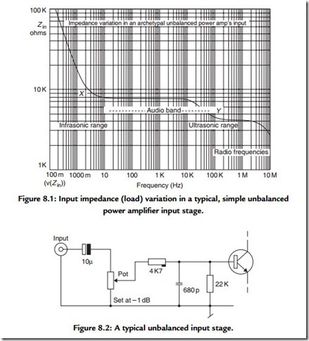
Figure 8.1 shows how the input impedance of a typical, minimal power amplifier with an unbalanced input (Figure 8.2) varies across the frequency range. A 10kΩ gain control is
assumed and is here backed off just ldB. Note how the impedance in most of the audio band is almost constant at the scale used. Then notice how the impedance drops off (so the loading increases) at high audio frequencies, and more so at higher radio frequencies (Y). At low frequencies, if anything, the load impedance increases (X).
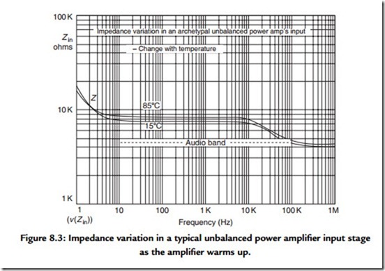
Figure 8.3 shows how the same input stage’s impedance varies (without changing anything else) as temperature is changed from 15° to 85°. In other words, what can happen to the input impedance when an amplifier is “cooked?” For the most part, impedance increases, which will do no harm. However, in live work it might just alter a howl round threshold, as the higher load impedance allows the signal voltage to rise ever so slightly.
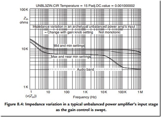
Figure 8.4 shows how the input impedance typically varies as the gain is adjusted. Because the change with each 30° rotation step is nonmonotonic, Zin goes up and then comes down, as you might expect. A 10kΩ log pot is assumed.
Ideally, an amp’s input impedance would remain constant despite these changes. In unbalanced circuits, there is not much harm as long as any change in impedance is gradual and stays above certain limits, and anything that isn’t like this happens well above (or even further below) the audio band. Staying constant is far more important in balanced circuits.

