OPEN- AND CLOSED-LOOP CONTROL
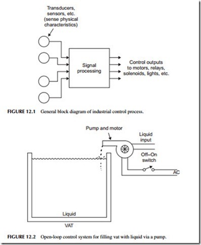
The basic industrial control process is illustrated in Figure 12.1. Electrical inputs, such as switches, sensors, or other devices, are used to initiate an electronic control process. The signal-processing circuits generate control output signals that are used to operate the industrial machines. This basic process is known as open-loop control. The typical device being controlled by the output signals is an electric motor that operates a machine. Other outputs could operate lights, relays, solenoids, or a variety of other devices.
Transducers, sensors, etc. (sense physical characteristics)
Open-Loop Control
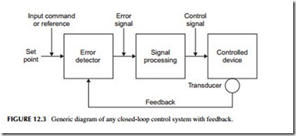
A simple example of an open-loop control system is shown in Figure 12.2. The input is a switch that applies electrical power to a motor. The motor, in turn, operates a pump that causes liquid to be put into a vat or tank. As soon as the vat is full, the operator turns the switch off. The basic control process in this system is simply turning power off and on to control the pump. The operator visually monitors the level in the vat until the correct level is reached.
Closed-Loop Control
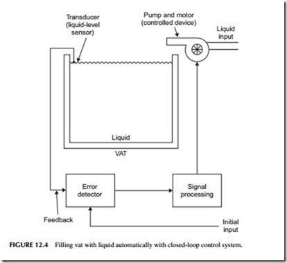
An improved form of industrial control system is illustrated in Figure 12.3 . It is known as a closed-loop control system. The system is given an initial input
reference called the set point. The set point is usually a voltage that represents some physical value that is to be achieved. It is applied to an error detector that compares this input to a signal from the controlled devices. If the two signals are different, an error output is produced. This error signal is processed (usually amplified), and an output control signal is derived from it. It is this output signal that operates the controlled device. A transducer monitors the control- led device to see that the desired outcome is obtained. The signal from this transducer is called feedback. The feedback signal is compared to the input to produce the error signal. The control signal operates the controlled device until the error is reduced to zero. At that time, the desired output condition, where the feedback equals the set point, is obtained.
The key to closed-loop control is the feedback. Feedback signals tell the system whether the machine is performing correctly. The feedback signal allows the system to adjust itself in such a way that the desired output is con- tinuously accomplished. Control is automatic.
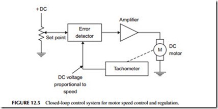
A closed-loop version of our system to fill a vat with liquid is shown in Figure 12.4. An initial input signal is applied to start the process. If the vat is not full, the transducer will sense it and send a signal to the error detector that says the liquid level is low. The error detector generates an output signal that is processed and used to start the pump motor. The motor rotates the pump, which puts liquid in the tank. When the vat is full, the sensor will generate a signal that is sent to the error detector. The error is now zero, so the pump motor is turned off.
The primary benefit of a closed-loop control system is that its operation is automatic. In the open-loop system, an operator has to turn the system off and on manually to fill the tank. In the closed-loop control system, the operator gives an initial input, called the set point, to which the error detector will com- pare the feedback signal from the sensor. He or she turns the system on. From that point on, operation is automatic. The pump turns itself off when the vat is full. If the liquid level drops below the desired level due to usage, the sensor indicates a low level and automatically turns on the motor so that the pump will again fill the tank. When the tank is full, the unit shuts off by itself.
Most industrial control systems are closed loop to make them automatic. And your home has some as well. Your toilet flusher is a closed loop as is your heating and air conditioning (HVAC) thermostat. Appliances like your washer, dryer, and dishwasher are other examples of closed-loop control. All of them contain a microcontroller with sensors, timers, and feedback to make them totally automatic.
Controllers
While many industrial control applications are implemented with simple control circuits, most industrial control is carried out by specialized instruments called controllers. These units accept inputs from sensors, condition them, process them, and then generate output control signals.
A good example of an analog controller is one used to control the temperature in a system. A resistive temperature sensor is used to monitor the temperature of the liquid in a pipe. If the temperature goes up, the sensor out- put goes up. This is sensed by the controller circuitry. Inside the controller, a comparator is set to a desired temperature threshold. Should the temperature exceed a specified set point, the controller will turn off the device heating the
pipe and liquid. Should the temperature drop below another set point temperature, the controller will turn on the heating device in an effort to maintain the set point temperature. While the heating element will be turning off and on, it will produce the desired average overall temperature.
A continuous analog controller will provide proportional control rather than an off/off response. For instance, suppose that you want to control the speed of a motor. The system depicted in Figure 12.5 does this. You want the motor to stay set to the speed you want, say 1200 rpm. A pot connected to a voltage represents that speed value. The voltage is applied to an error detector along with the feedback input from a tachometer. A tachometer is a device that senses rotational speed and develops a proportional DC voltage. That voltage is sent to the error detector and compared to the set point. If they are different, an error voltage is developed. This voltage is then amplified and applied to the motor. The speed of a DC motor is proportional to the voltage applied to it. So if the motor slows down, the error voltage is increased and that is amplified and applied to the motor speeding it up to compensate for the speed drop. A speed up in the motor produces an increased tachometer output. The resulting error signal causes the motor speed to drop until the error is zero. With such a circuit, the motor speed remains constant.
An analog controller is a product made up of the set point pot, error detector, and a selection of amplifiers whose gain can be varied and an output amplifier that can drive the motor or other device. Many different types of commercial electronic controllers have been developed to monitor and control physical characteristics such as pressure, physical strain, weight, liquid flow rate, physical position, or liquid level in a tank. Digital controllers that contain a microcomputer are also available.
Related posts:
Incoming search terms:
- closed loop system in industry
- machinery equipment online mail
- open loop system with industrial example
- industrial applications of closed loop control system
- open loop system in industrial
- related:https://www youtube com/watch?v=vbpdzsTUkMQ control system pdf
- water closet system open loop or closed loop
- industrial application of open loop
- Machinary and parts mail
- Loop tutorials industrial electronics
- Machines that use closed loop control system in an industrie
- Machines that use open loop control system in an industrie
- open and closed loop relaus
- open and closed system appliances
- open loop system examples
- which machineries used clossed loop control system
- open loop system in industrial use
- open loop system in industry
- openloop system in processing industries
- Operation of a closed loop level control system
- program controlled automatic looped machine
- some closed loop electric appliance
- intelligent closed loop control system reagent grinding
- industrial uses of open loop system
- industrial examples of closed loop system
- Example of close loop system use in industry
- electric machine control loop
- closed loop system in processing industries
- closed loop control system equipments
- closed loop control examples
- Close loop con
- application of open looppp system in industry
- application of closed loop system in industry
- example of closed loop system in industry
- examples of industrial machines that are open loop
- industrial examples of closed loop control system
- industrial elctronic open loop control system
- Industrial Control System containing open and closed loop control
- industrial application of closed loop control system
- good example of closed loop system
- give texamples of aclosed loop cobtrol systems used in industries
- examples of open loop sytem in manufacturing industries
- EXAMPLES OF OPEN LOOP IN INDUSTRIAL
- appliances of close loop control


