LOUDSPEAKERS
We have progressed a long way since early designers fixed a crude horn to a telephone earpiece to make the first loudspeaking telephone. Since then, many other drive principles have been adopted to further the quest for perfect reproduction. The science of loudspeakers has been refined to the point where the response of a drive unit, at least at low frequencies, can be predicted with great accuracy. Just as the choice of a microphone dictates what goes into the recording, the loudspeaker decides the quality of the output.
IDEAL LOUDSPEAKER
There are a number of interrelated factors that must be considered in designing transducer for converting electrical energy into airborne acoustic energy. These include electroacoustic efficiency, uniformity of frequency response, linearity of amplitude response, transient response, power handling capacity, size, durability and cost. An ideal loudspeaker:
(i) would have an electroacoustic efficiency approaching 100 percent.
(ii) would have an acoustic output response that is independent of frequency over the entire audible range.
(iii) would introduce neither harmonic nor intermodulation distortion into its output.
(iv) would faithfully reproduce transients as well as steady input signals.
(v) would be capable of producing a nondirectional radiation pattern.
(vi) would be of as small a size as is possible considering the required acoustic output.
No single transducer has been designed that is capable of satisfying all the above requirements. Out of many devices developed for the radiation of acoustic energy into air, the two most widely used are the direct-radiator or dynamic loudspeaker and the horn loudspeaker. Both of these loudspeakers utilise the electrodynamic coupling that exists between the motion of a vibrating surface, called the cone or diaphragm and the current in a so called voice-coil. Additional types of electromechanical coupling that are used for this purpose include electrostatic coupling in electrostatic loudspeakers and electromagnetic coupling in telephone receivers.
The speaker system itself can be divided into three functional parts:
(a) The electromagnetic part, consisting of the voice coil and the field magnet. Audio frequency electric current in the coil causes mechanical motion of the cone or diaphragm on which it is mounted. This part is often referred to as the driver or motor of the system.
(b) The mechanical part, on which the driving coil is usually mounted and which is set into mechanical motion by the audio frequency electric current in the driving coil.
(c) The acoustic part, which transmits the sound energy developed by the mechanical part of the area served by the system in the most efficient and faithful manner possible. This takes the form of a baffle or enclosure with a horn being a form of enclosure.
A complete understanding of the operation of the speaker systems requires a sufficient view of the flow of acoustic energy from the ouput amplifier stage to the listener.
BASIC LOUDSPEAKER
When broadcasting first began, the only available devices for converting sound energy into electrical energy, and vice versa, were those used in the ordinary telephone. Microphones were usually of the carbon type. The hearing device, or telephone receiver, was a simple electromagnet energised by electrical signals. These signals caused a thin sheet of magnetic material (the telephone diaphragm) to vibrate in synchronism. Wearing headphones, however, was not exactly conducive to listening pleasure, besides the reproduction wasn’t of the best quality. So, engineers started to search for some sort of hearing device that could be separated from the head of the listener and still supply enough volume to make listening easy. Hi-fi wasn’t really thought of at that time.
The two problems faced by the early engineers were; amplifying the electrical signal enough to drive the loudspeaker, and designing an off- the-head speaker that could reproduce the electrical signals in the form of sound.
One of the first speakers designed was simply a large horn attached to an ordinary telephone earphone mechanism. This speaker had fairly good volume, but frequency response was poor.
In another early design, a vibrating reed was used instead of the thin disk of magnetic material (the diaphragm of the earphone). The free end of the reed was attached to a speaker cone, and the reed’s vibration caused the whole cone to vibrate.
A third type of speaker had a balanced pivoted armature located between a pair of magnets. Electrical impulses through the magnet coils caused up-and-down vibration. The armature movement was mechanically coupled to the speaker cone with a stylus, thus producing the sound.
There are three types of speakers in modern use: crystal, electrostatic
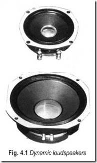
(condenser) and electrodynamic (or simply dynamic) speakers. Dynamic loudspeakers are illustrated in Fig. 4.1.
CRYSTAL LOUDSPEAKERS
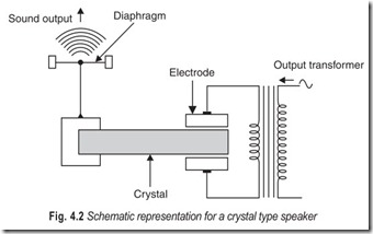
Rochelle-salt crystals have the property of becoming physically distorted when a voltage is applied across two of their surfaces. This property is the basis of the crystal type of speaker driver, illustrated in Fig. 4.2.
The crystal is clamped between two electrodes across which the audio frequency output voltage is applied. The crystal is also mechanically connected to a diaphragm. The deformations of the crystal caused by the audio frequency signal across the electrodes cause the diaphragm to vibrate and thus to produce sound output.
Crystal speakers have been impractical for reproduction of the full audio-frequency range because the input impedance is almost completely capacitive. Thus it is difficult to couple power into them. At high audio frequencies, the reactance becomes lower (Xc = 1/2π f C) and the relative amount of power smaller. In the bass range, stresses on the crystals are very great, and crystals have been known to crack under stresses.
Consequently, crystal units have found some use in tweeters (the high-frequency portion of dual- speaker units) and rarely even in this application because their response is not linear.
ELECTROSTATIC (CONDENSER/CAPACITOR) LOUDSPEAKERS
This type of speaker operates on the principle that a dc voltage between two parallel metal plates causes these plates to attract or repel each other. The amount of attraction or repulsion depends on the applied voltage. If one of the plates is a flexible metal, it will bend. But the amount of attraction and repulsion is not directly proportional to the voltage applied.
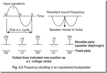
For example, consider the movable and fixed plates of Fig. 4.3 with no voltage applied. Now suppose we apply a slowly varying ac voltage to both plates. As the voltage increases from zero, the potential difference between the two plates also increases. This, in turn, produces an increasing force of attraction between the plates, so that the movable plate bends towards the fixed plate. As the ac voltage decreases once more to zero, the attractive force decreases, and the movable plate moves back to its original position. But, now we have the second half of the ac cycle, in the negative direction. All that this means to the metal plates is that the positive and negative voltages have switched plates. The attractive force is still there, and it is still the same. So, we get another bend in the movable plate on the negative half of the ac cycle. Thus, for one full cycle of ac we have two bends in the movable plate, in effect a frequency doubling. A 2 kHz signal would give us a 4 kHz note.
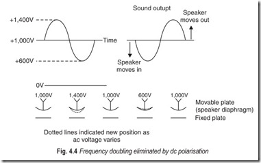
To overcome frequency doubling, we polarise the speaker, that is, we apply a high voltage (1,000 volts or so) as a sort of dc bias, (Fig. 4.4). The voltage exerts a steady attraction between the two plates, so that now—with no signal—the movable plate is bent slightly toward the fixed plate.
Now suppose we apply a 400 V dc audio signal to the speaker. As the positive half cycle of the signal increases from zero the voltage between the plates rises from 1,000 V toward 1,400 V and the movable plate bends from its original position toward the fixed plate. As the ac passes its peak and returns to zero, the voltage between the plates drops from 1,000 V to 600 V. Instead of moving again toward the fixed plate, the movable plate moves farther away. So we have a situation in which the bending of the movable plate is identical to the ac swing and there is no frequency doubling.
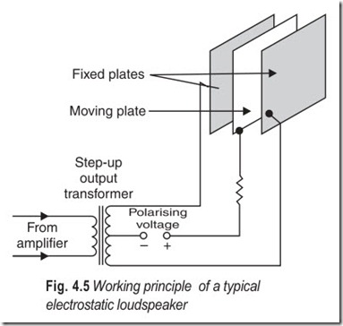
A detailed view of a modern electrostatic speaker is shown in Fig. 4.5. The practical speaker of today uses push-pull, with a built-in step-up transformer to work from the ordinary 8 ohm amplifier output tap.
The polarising voltage is applied to the centre or movable plate through a resistor that keeps the voltage stable during variations in the signal voltage. The signal voltage is applied to the two outside plates. Because the diaphragm is centered between the two plates that attract it equally, there is no bending when there is no signal. Also, because of the push- pull action the diaphragm can move twice as far in response to signal voltages for the same amount of compression of the dielectric material.
The major weakness of the electrostatic speaker requires the dc bias is that it to be much larger than the applied audio signal. In practical speakers, 1,000 to 1,200 volts may be used. Further, when we get into the bass frequency ranges, a great deal of power would be required to get enough output. To produce such power, the speaker
area would have to be very large. So, even though full range electrostatic speakers have been constructed , in practical use electrostatic speakers have been mostly confined to frequencies above 1,000 Hz.
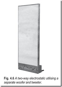
The step-up transformer and the high voltage polarising supply is usually built right into the modern electrostatic. Often the electrostatic unit and its matching woofer are sold together as a complete system.
Some high class systems use electrostatics to reproduce the high frequencies. Koss uses electrostatics on some of their stereo headphones.
DYNAMIC LOUDSPEAKERS
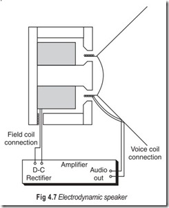
There are two varieties of dynamic loudspeakers : electrodynamic and permanent magnet (PM) speakers. Both work in exactly the same way, the difference is in their construction.The electrodynamic speaker has a soft iron magnetic circuit, non-retentive of magnetism, around whose centre leg, a large, multilayer field coil is wound, as shown in Fig. 4.7. When dc flows through this field coil, it magnetises the iron core. A magnetic flux field directly proportional to the strength of the current through the coil is thus set up across the airgap. The iron core is not permanently magnetised, it stays magnetised only as long as current flows through the field coil.
Improvements in permanent magnet materials have made the electrodynamic speaker practically obsolete, but some still exist in vintage radios. Note that these use the field coil as part of a choke filter in the power supply, a good example of killing two birds with one stone. The electrodynamic speaker has disappeared completely, so far as hi-fi is concerned, the permanent magnet speaker reigns supreme.
PERMANENT MAGNET LOUDSPEAKERS
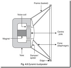
The most popular type of loudspeaker today is the permanent magnet dynamic type. Because of its comparative simplicity of construction and design, the precision that may be built into it, the ease with which it is interfaced with other equipment, its easy adaptability to many different applications, and its comparative freedom from electrical trouble, the dynamic loudspeaker has found acceptance in all kinds of reproducing systems. It is found in the smallest pocket radios and is a major component of the most elaborate theatre systems (See Fig. 4.8).
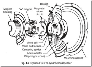
Just about all hi-fi woofers are of the permanent magnet (PM) type. Exploded view of the PM cone type speaker is given in Fig. 4.9. The cone (diaphragm) is energised by a moving coil. The woofer’s magnetic field is supplied by a permanently magnetised and highly magnetic alloy instead of the iron-cored coil used in electrodynamic speakers.
The PM speaker contains a very light coil of wire affixed to the diaphragm and located concentrically around, within, or in front of the centre of the permanent magnet. The coil (voice coil) is free to move in the field of the magnet. Electrical impulses, varying at an audio rate, are applied to the voice coil by the amplifier. Because these impulses are constantly changing in amplitude and direction, a changing magnetic field is set up in the voice coil. This field reacts with the constant field of the permanent magnet. The result is that the voice coil moves further into the gap when the fields are opposite and attract, and farther out of the gap when they are alike and repel. This causes an in-and-out movement of the diaphragm; consequently, we obtain sound waves from electrical impulses. The speed at which the coil and diaphragm vibrate depends upon the frequency of the impulses. The distance that the diaphragm moves in and out depends on their amplitude.
LOUDSPEAKER CONSTRUCTION
The voice-coil is wound on a cylindrical form. The diaphragm, usually made from a special paper, is attached to the outer rim of the voice coil form. Some speaker systems utilise speakers that have aluminium diaphragms. The metal prevents the effects of humidity changes and helps dissipate the thermal energy present when the speakers are driven at high levels by powerful amplifiers. High quality speakers use diaphragms composed of titanium, aluminium, and paper to achieve the maximum stiffness required for their mode of operation.
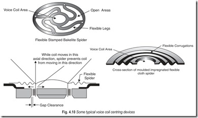
The outer edge of the diaphragm is cemented to the speaker’s metal frame (basket). The permanent magnet is located concentrically in the back of the voice coil. To prevent the voice coil from shifting, it must be supported adequately and maintained at dead centre; however, it must be free to move in and out. This is accomplished by the flexible spider, Fig. 4.10. With the latter cemented firmly in place, the voice coil is free to move in and out, but not vertically or laterally.
PERMANENT MAGNET
The strength of the permanent magnet largely determines both speaker efficiency and quality of reproduction. The magnet must furnish the most powerful magnetic field in order to maximise the voice coil movement for any given signal. In general, the stronger the magnet, the better the power handling capacity of the speaker, and the better the reproduction.
Woofers are speakers designed to reproduce the bass, or low frequency, portion of the audio-frequency spectrum. For woofers, the designer does not choose the strongest available magnet as adding more magnetic flux will reduce the bass performance of a woofer because the moving system becomes overdamped. The designer, therefore, chooses the magnetic flux level that provides the best compromise between efficiency and bass response. For a hi-fi speaker system this is very seldom the level at which the magnetic flux is as strong as possible.
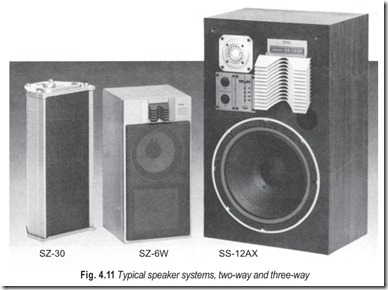
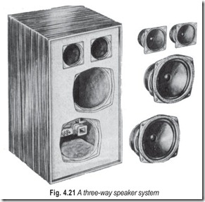
Mid-range speakers are designed to reproduce the mid-frequency portion of the audio frequency spectrum. Tweeters are speakers designed to reproduce the treble, or high frequency portion of the audio frequency spectrum. As far as the magnetic flux in mid-ranges and tweeters is concerned, the designer usually does try for the strongest flux field possible, of course, within the cost restrictions. A typical speaker system is shown in Fig. 4.11.
The mid-range speaker in a three-way system is often referred to as a squawker.
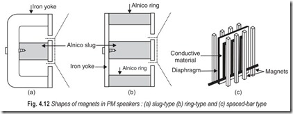
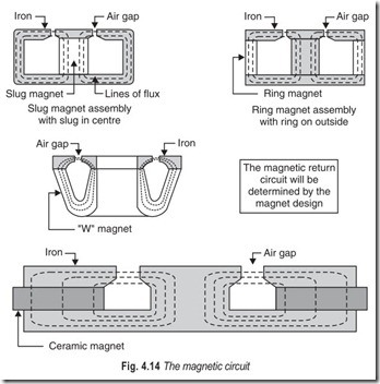
Permanent magnets in speakers are available in various shapes. One example is the magnet in the form of a solid cylindrical slug, as shown in Fig. 4.12 (a). A U-shaped iron yoke completes the magnetic circuit, except for the voice coil gap. Another type, similar in outward appearance, uses a hollow cylindrical slug with an E-shaped yoke, with almost the entire magnetic circuit composed of Alnico [Fig. 4.12 (b)]. A third type, Fig. 4.12 (c), uses spaced permanent magnets. Here, instead of a voice coil, the diaphragm itself (which consists of Mylar stretched taut over a frame that has copper wire glued in a square-wave pattern to its surface) is placed in the magnetic field.
Ceramic magnets have several advantages over metal magnets. They are lighter, stronger, and less expensive to produce than metal magnets of comparable size. Their development has resulted from the need for lighter and smaller magnets, but ones that have strong fields. Their principle of construction is simple. During the period when the ceramic is moulded to its final shape with the elimanation of impurities, the ceramic is subjected to a very strong magnetic field. Once, the ceramic is cooled, this magnetic field is retained, and we have a very strong permanent magnet.
VOICE COIL
The voice coil is the only thing present in the speaker which carries electrical current or signal. It is energised directly from the amplifier. The voice coil, as its name implies, is the part of the speaker that
does the talking.
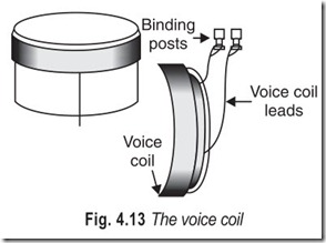
The voice coil, Fig. 4.13, consists of several turns of wire wound on a supporting bobbin. Depending on the functional design of the loudspeaker, the coil itself may be copper or aluminium wire, although insulated aluminium ribbon is also used. In case of the latter, the ribbon is wound on edge with the flat surfaces of neighbouring turns adjacent to each other and all the turns held together by a binding cement.
The bobbin, or the voice coil former upon which the wire is wound, may be made of a strong grade of thin paper, wound around on itself several times to provide a rigid cylinder. Sometimes the voice coil is wound on aluminium or duraluminium formers, and in some designs the voice coil formers are made of rigid paper, reinforced by an aluminium ring around the outer edge. In case the voice coil wrap get twisted, it might contact the core of the magnet. When this occurs the rasping noise develops, rendering the speaker useless. To offset this possibility, many speakers now contain wrap resistant aluminium base voice coils.
The voice coil of a dynamic loudspeaker can speak only when it is immersed in a magnetic field. Such a magnetic field may be produced by constructing an iron loop with the magnet in one section and an air-gap in another, as shown in the magnetic circuit in Fig. 4.14.
The magnet is never charged unless it is in its completed mechanical structure. As soon as the magnet is charged, it sets up a complete magnetic field. When electrical signal current from the amplifier flows through the voice coil, we have a varying magnetic field of the voice coil in close proximity to the fixed magnetic field of the permanent magnet. Motor action will thus be developed. Because of the interaction of the two fields the voice coil moves one way or the other, depending on the direction of the signal current as well as the direction of the magnetic field due to the permanent magnet.
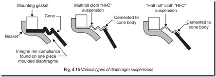
The voice coil is attached to the diaphragm which actually fans the air into motion. In order to allow the diaphragm to vibrate back and forth freely, it is necessary to provide it with some sort of flexible support that will allow it to have motion yet keep it vibrating in a true axial direction. The diaphragm is provided with a flexible area at its outer edge sufficiently compliant to allow the diaphragm to flex in and out.
These compliances, Fig. 4.15, may be either half-roll or multi-roll and are cemented to the main body portion of the cone. They are referred to as high compliance type (HI-C) and, because of their looseness, permit the cone to move over abnormally large excursions.
Sometimes the rim compliance is accomplished by providing an annular ring of soft chamois leather, which is cemented both to the basket edge and to the paper diaphragm. A general term used for this edge compliance is the surround because it literally surrounds the speakers.
LOUDSPEAKER IMPEDANCE
The impedance looking into the voice coil is not only the self-impedance of the coil itself but a combination of the self-impedance and the more important reflected acoustic impedance.
A parallel may be drawn with a transformer or motor. Each of these devices draws a small current when operating unloaded, indicating a relatively high input impedance. When the transformer secondary is loaded by an electrical resistance, or the motor shaft is coupled to a mechanical load, the input current rises and the input impedance of each device is lowered in proportion. In other words, the load impedance has been reflected into the input circuit in each case, whether it is an electrical load on the transformer or a mechanical load on the motor.
The voice coil winding is similar to any other coil in that, it has resistance (due to the wire used in the winding), inductance (due to the turns of the windings), and a small amount of capacitance (distributed between the turns). The resistance and the reactance of the coil combine to form the self-impedance of the winding without any impedances coupled into it from its association with the other parts of the speaker.
The self-impedance of the voice coil is modified by the reflected impedance of the load on the diaphragm. Mechanical inductance is called inertance. The degree to which the air tends to stay at rest is a measure of its inertance. It is the inductance of an electrical circuit which provides electrical inertia and it is the current which tends to stay at rest or in motion in proportion to the amount of inductance present. Mechanical inductance when applied to the air is also referred to as acoustic inductance. The term inertance is especially applied to the acoustic system and the air in contact with the diaphragm. The mechanical inductance of the cone and voice-coil structure and of its suspensions is also a factor in the input impedance to the voice coil, and is reflected back to it with the acoustic inertance.
Mechanical capacitance is called compliance. When force is applied to the spring, energy is stored in it. When the spring is released, the stored energy is also released. This is exactly what happens electrically in a capacitor in which energy is stored by the flow of current into the capacitor by application of a voltage. The applied voltage is analogous to the applied mechanical force, and the resulting current is analogous to the motion or change or displacement of the spring. In mechanical systems, we call this effect mechanical compliance. The cone suspensions act as springs and offer resistance to cone motion which increases as cone displacement increases. The suspension compliance is the main capacitive effect, although the springiness of the air load and the cone and voice coil structures during flexing add other capacitive factors. When applied to the air, this effect is called acoustic compliance.
Mechanical resistance is friction; the resistance force developed when two or more surfaces, layers, or group of particles rub together. In a speaker of the dynamic type, there are no material surfaces which rub together. Purely mechanical resistance arises in the friction within the cone and suspension materials when they flex during operation. Acoustic load (useful resistance component) is developed by the friction of the particles and layers of the air surrounding the cone when they bear upon each other or along the mechanical surfaces of the speaker assembly when motion is imparted to the air in the form of acoustic vibrations.
Mechanical components of impedance have the same relationships among themselves as exist among their counterparts in the electrical circuit. Power is dissipated only by the resistive component. The inertance and compliance produce mechanical reactance which varies in the same way as electrical reactance varies.
ACOUSTIC IMPEDANCE AND RESONANCE
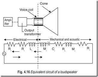
The resistances and reactances of the system (including acoustic, mechanical and electrical effects) combine in the effective impedancelooking back into the voice coil. This combination is best visualised by anequivalent circuit illustrated in Fig. 4.16. The efficiency of power transfer is dependent on the proportion of the impedance represented by RA, which represents actual acoustic power dissipated in overcoming air friction and in radiating the acoustic power.
As in a purely electrical system, the capacitive reactance CC resonates with the combined inductiveeffects LV , MC and MA at some frequency called the resonant frequency of the speaker. At the resonantfrequency, all reactance is cancelled out of the system and output and efficiency are far greater than what they are for other frequencies.
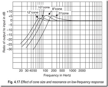
The curves of Fig. 4.17 show the effect of speaker resonance on response. The response rises to a peak at the resonant frequency, then it falls rapidly at lower frequencies. The shape of the response curve shows how the resonant frequency can be used as an indication of the limit of low-frequency response.
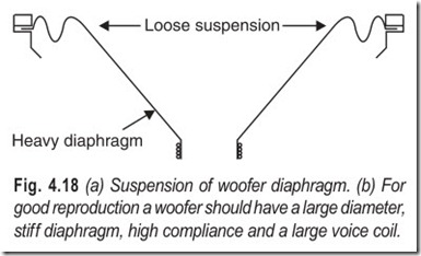
The size of the cone (Fig. 4.18) is important because it influences both the low-frequency response and power-handling capacity. The larger the cone diameter is, the greater the power capacity for all low-frequency components combined and the better the low-frequency response. However, such improvements are not necessarily derived from larger cones unless the voice coil is appropriate. The acoustic impedance offered to the cone rises as the cone is made larger; the voice coil impedance must then also be made larger for proper energy transfer and efficiency. The major portion of the audio frequency signal power is in the low-frequency components, so that the overall power-handling capacity is also improved.
Undesired sharpness of the resonant peak can be lessened by electrical, mechanical, or acousticdamping. Damping is the addition of a resistive load. One method of providing damping is through proper design of the output stage of the amplifier. Another method of providing speaker damping is through proper design of speaker enclosure.
WOOFERS
There are two types of low-frequency speaker, the commonly known woofer, and the more recent addition the subwoofer. The latter is used for the reproduction of frequencies below those produced by the woofer, and it is generally purchased as an add-on to an existing system.
The low-frequency speaker provides the bass of any hi-fi system. Its sole purpose is to reproduce the low-frequency notes of the program source. The prime requisite for low-frequency reproduction is a large diaphragm, the larger the better. The smallest diaphragm for any halfway decent woofer is 8 inches; for a subswoofer it is 12 inches. In addition to large size, the diaphragm must be of fairly heavy construction. Light diaphragms just can’t hold up under the vibrations encountered under the lower audio ranges.
A woofer must be able to vibrate back and forth very easily, i.e. have high compliance. One way to accomplish this is to have the diaphragm loosely connected to the frame. The gasketing that holds the periphery of diaphragm to the
frame/basket is fastened so that it barely keeps the diaphragm from slipping loose, but no more as shown in Fig. 4.18. With this construction it takes less force (acoustical power in this case) to move the diaphragm any particular distance (less power required for a given excursion).
Rather than the loose suspension system, the cone is supported by a very flexible material so that it can be moved very easily by the voice coil. The suspension is tight but the sine wave at the diaphragm edge is made very flexible.
The large speakers have more extended lows, the smaller ones more extended highs.
A woofer must also have a large voice coil to handle considerable heat. The larger the voice coil, the more the current produced by the amplifier output circuit and, therefore, the more the power the woofer can handle.
Finally, a strong magnet can be of great help to move the heavy voice coil and cone assembly too well. The better the woofer, the heavier the magnet assembly (unless it’s ceramic).
To sum up, a good woofer must have a large, heavy diaphragm, a strong magnet, high compliance, and a large voice coil.
MID-RANGE AND EXTENDED-RANGE SPEAKERS
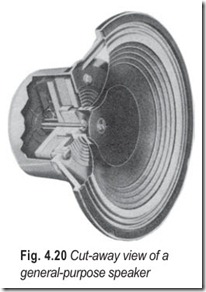
The mid-frequency loudspeaker is supposed to have a good response at the frequencies located between those covered by the woofer (low-frequency speaker) and the tweeter (high-frequency speaker). However, some extended-range speakers can be used as general purpose units. An adequate general purpose speaker, Fig. 4.20 must have good response at both the low and the high ends of the audio range, not to mention in the middle.
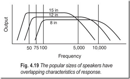
Tests by various manufacturers reveal the following data: A 15 inch diameter loudspeaker will give excellent low-frequency response but will be sadly deficient in the highs. A 12 inch diameter unit will still give good low-frequency response, halfway decent middle frequency response, but not too good treble response. The 8 inch unit, one of the most popular today, is the smallest that will permit fairly good response at low frequencies, and good response at the middle and high frequencies. This is shown in Fig. 4.19.
Conventional extended range speakers are now available in frequency range 45 to 15,000 Hz, although they need a good enclosure to cover the range. To obtain this type of response, the loudspeaker must be designed in away that the diaphragm will vibrate well at the low and middle frequencies, yet have some sort of compensation to permit good response at high frequencies. A three-way speaker system is shown in Fig. 4.21.
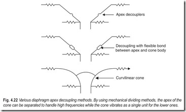
The top illustration in Fig. 4.22 shows the converse type of diaphragm. Here the curvature of the diaphragm allows the apex to isolate itself without the need for special decoupling devices. The centre diagram shows the apex decoupler built right into the apex area. The lower diagram illustrates the joining of two discrete diaphragms to each other by means of a flexible connection. Thus one diaphragm can vibrate while the other one doesn’t.
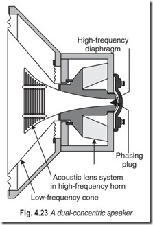
In the duplex type or coaxial speaker, we have a high-frequency horn centered within the framework of the low-frequency speaker, as shown in Fig. 4.23. However, there is only one voice coil; thus it more properly falls into a single-unit extended-range category. The switch from high to low-frequency response is made by a mechanical crossover built right into the speaker framework.
HIGH FREQUENCY LOUDSPEAKERS
There are two main types of high frequency speakers; the well-known tweeter and the more recent supertweeter. Supertweeters can be add-ons or they can be integral with the system. Six basic high-frequency speakers (tweeters) exist.
(i) The cone is a physically disincentive version of the woofer.
(ii) The dome, so called because of its dome-shaped diaphragm.
(iii) The horn, so named because it is a horn.
(iv) The Heil air-motion transformer which uses the principle of lever in its operation, named after its inventor, Dr. Oskar Heil.
(v) High polymer molecular-film tweeter, uses the piezoelectric effect for its principle of operation (used exclusively by Pioneer).
(vi) The electrostatic tweeter works on the principle of attraction or repulsion between two metal plates.
CONE TYPE TWEETERS
Since tweeters must reproduce high-frequency notes, they must resonate at high frequencies. High resonant frequencies are obtained with lightweight, stiffly supported mechanisms. To make the diaphragm of a cone- type tweeter light, it must be small. When we reduce the size and weight of the diaphragm we must, in turn, reduce the size of the voice coil also. Luckily, high frequencies carry only a comparatively small amount of electric power, therefore, the small voice coil is not subjected to electrical overload. Without exception, it is wound with light weight wire such as aluminium wire or ribbon. The lightness of the moving system provided by aluminium makes the high frequency response much better than if copper were used.
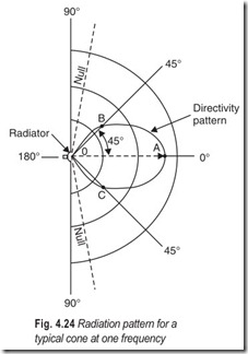
Cone type radiators tend to concentrate radiation of the high frequency components of sound in a narrow cone about the axis of the radiator. The degree of directivity of speaker is indicated by a directivity pattern in Fig. 4.24. The axis of the radiator is considered the reference line with an angle of zero degrees. Directivity patterns are normally shown as a top view in the horizontal plane through the radiator axis. A cone in free space should have the same pattern in a vertical plane.
The line OA in Fig. 4.24 indicates by its length that the sound radiated along it is a maximum in comparison to that in any other direction. At an angle 45°, the line OB is a measure of the relative sound intensity in that direction. Since OB is only half as long as OA, a listener along OB would listen only about half the volume compared to what a person along OA. At angles near 90°, the pattern indicates minimum (zero) radiation. In any practical setup, such a zero area would not exist because sound waves reach there by reflection.
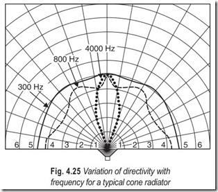
Because, directivity normally varies considerably with frequency, a complete diagram (Fig. 4.25) must show separate patterns for each of at least several frequencies. Fig. 4.25 depicts variation of directivity with frequency for a 12-inch cone, assuming that the speaker is mounted in an infinite baffle. Notice how much narrower the radiation pattern is at highs than at lows.
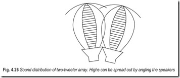
A single cone-type tweeter distributes high-frequency sounds unevenly. It lobes the higher frequencies directly out in front and tends to cause a drop off at the sides. This effect can be overcome by arranging two or more cone tweeters as shown in Fig. 4.26. In this way, overlapping individual lobes from separate speakers cover the listening area.
DOME TYPE TWEETERS
Uniformly dispersed flat energy response begins with a speaker system’s ability to radiate sound at all frequencies evenly in all directions. Even dispersion of sound energy means that the sound emanating from the program source will be heard same by listeners in all parts of the room.
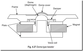
For low frequency sounds this problem of dispersion is not of practical consequence, since they are very nearly omnidirectional. The limiting factor for high-frequency sounds is that a speaker will begin to be directional when its circumference equals the wavelength of the frequency being reproduced. Directionality increases as the wavelength decreases with respect to the speaker’s dimensions. The laws of physics dictate the most direct approach to the problem of even dispersion of high-frequency energy; the drivers used must be as small as possible. Dome tweeters, Fig. 4.27, are designed according to this principle in order to use these physical laws to the listener’s advantage.
HORN TYPE TWEETERS
To obtain reasonable output from a loudspeaker, we must vibrate large amounts of air. For this, we must usually have fairly large vibrating surfaces, such as the cones in woofers. The larger the cone surface, the greater the output. But the tweeter’s cone (diaphragm) must be small to attain its high-frequency response. Thus only a small amount of air can be moved, reducing the output power.
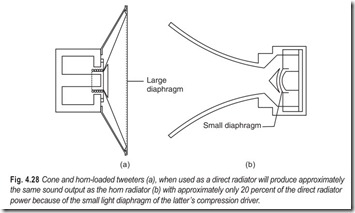
We can increase the acoustic output from any type of diaphragm if we couple directly to a horn, converting the system to a horn-loaded one. Fig. 4.28 shows the relative difference in size between the diaphragms of a cone-type tweeter and a horn-loaded one. The driving force of the voice coil of the latter is distributed between the small mass of the diaphragm and the mass of air in the horn. Since air weighs much less than paper or metal the overall load on the voice coil, for the same acoustic output as that of the cone type tweeter, can be greatly reduced. Also, for the same electrical input, the output of the horn loaded system is greater.
A horn is a tube so flared (tapered) that the diameter increases from a small value at one end called the throat to a large value at the other end called the mouth. Horns, Fig. 4.28 (b), have been used for centuries for increasing the radiation of the human voice and musical instruments.
The horn does acoustically what the cone does mechanically. It couples the small voice coil area to a large area of air. In this way, the horn acts as an acoustic transformer and converts the relatively high impedance at the throat and driver.
The horn is a fixed physical boundary for its enclosed column of air and does not vibrate itself. Acoustic energy fed to its throat must therefore be obtained from a vibrating diaphragm which converts mechanical motion from the driver voice coil to acoustic energy. Althoughthe cone-type radiator acts as both diaphragm and radiator and transducer from mechanical to acoustic energy, the horn acts only as a radiator, with both input and output energy being acoustic.
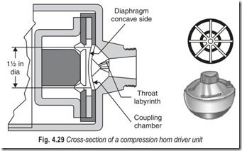
For maximum efficiency, horn driver units, such as the one shown in Fig. 4.29, are of the compression type. The back of the driver is completely sealed to provide a stiff air cushion behind the diaphragm. The sealed-in stiff air cushion is the underlying principle of acoustic suspension, or air-suspension speaker systems.
Any device that radiates energy into three-dimensional space has certain very specific directional properties. For example, an unshaded light bulb is pretty much omnidirectional, casting illumination in most directions. Like lamps, speakers have definite directional characteristics. At very low frequencies, any speaker is virtually omnidirectional. The directional characteristics of a speaker change with the frequency of the sound being generated, particularly with how the wavelength of the sound relates to the physical size of the speaker’s diaphragm. For a flat, circular cone, dispersion will be virtually omnidirectional for frequencies with wavelengths that are more than 4 times the diameter of the cone. Dispersion narrows to approximately 60° when the wavelength equals the diameter, and to 30° when the wavelength is half the diameter. A speaker with a 2 – inch radiating surface will be practically omnidirectional at 1,000 Hz, but will radiate a 10,000 Hz tone in a beam not much more than 30° wide.
Horns can be, and are, designed for controlled wide-angle distribution. Such horns are square or rectangular. These horns achieve similar results in different manners.
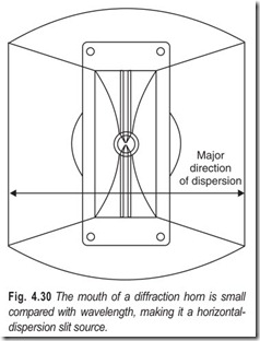
The diffraction horn, Fig. 4.30, operates on the principle that sound coming from a narrow-slit, which is small compared to the wavelength, emerges in a cylindrical wavefront pattern from the slit. That is, the wavefront diffracts out of the narrow slit. This type of horn has smooth angular response with no lobes or valleys in the sound pattern.
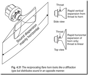
The reciprocating flare horn, Fig. 4.31, distributes the sound over a wide angle by reversing the direction in which pressure builds up within the horn. Its mouth construction is designed for horizontal dispersion. The horn first expands rapidly in the vertical direction, with practically no horizontal expansion. The sound pressure travelling along such a channel finds it relatively easy to expand vertically. But in trying to expand horizontally, the sound pressure builds up along the side walls of the horn. The result is that the sound comes out of the horizontally shaped mouth (i.e., the reciprocating flare), with exceptionally wide horizontal dispersion.
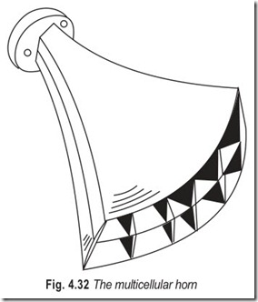
The sectoral/multicellular horn, Fig. 4.32 is similar to the reciprocating flare horn except that the mouth of the horn is compartmentalised to diffuse the sound over a wider area. What we have here is a sort of shower head that spreads the sound much like a shower head which spreads the water coming from it.
HIGH FIDELITY
There are several schools of thought concerning high fidelity – ‘play it exactly as performed’ school, ‘play it so it sounds real’ school, and ‘play it the way I like to hear it’ school. There is logic in all three approaches.
We must accept that there are as many types of high fidelity as there are listeners. In order to satisfy these concepts, it is necessary to provide a sufficient variety of component parts to make possible many different kinds of system. We have discussed speakers from the point of view of their general application to the hi-fi field.
There is no exact scientific operational definition of a hi-fi system as yet. Standards and specified measurements of performance of a system have not been possible to establish because of the limitations of the human ear and because of variations in human taste, room acoustics, system distortions, noise and comparative volume levels.
A commonly accepted concept of hi-fi- sound is that it is reproduced sound with a high degree of similarity to that of original or live sound that has travelled from a source and has undergone several conversions through a system or several systems. Hi-fi is felt to be achieved when the sound that is reproduced has negligible distortion from the original, when it has little extraneous noise, and when the volume levels and acoustical effects are pleasing to hear.
Reproduction of sound is something like a photograph. The picture cannot carry the original scene to the viewer in every detail. Some feature of the picture may be de-emphasised whereas other features may be emphasised intentionally, or distortion may be introduced for purely aesthetic reasons. Distortion of this type can greatly improve the illusion that the photographer is trying to create. In the same way, the picture can be spoilt by undersirable distortions and effects, such as poor focus, poor film and improper lighting.
Like photography, modern hi-fi techniques encompass controls for modification of the original (live) sound to compensate for certain defects and make provision to actually improve the effects according to an individual-listener’s tastes. Undersirable distortions, differences in comparative sound levels, and injection of extraneous noise are also held to a minimum so that the pleasing qualities of the original sound will not be reduced.
In addition, modern concepts of hi-fi take into consideration the listener, his ear mechanism, and his nervous response, plus his listening experience and training.
The word presence is used to describe the degree of realism of the reproduced sound. This term suggests that the reproduction is so real that the listener can feel the presence of the source that is causing live sound, even though the source may be extinct.
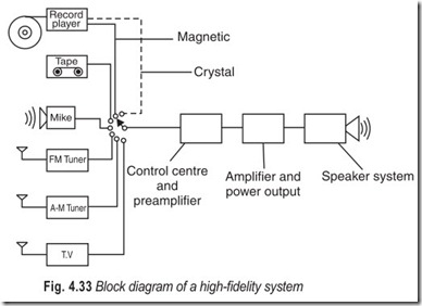
A complete hi-fi system may be divided into functional sections as illustrated in Fig. 4.33. The way in which the output differs from an input or a desired ideal output is called distortion. Distortion may be created in anyone or more of these sections. If more than one section is causing distortion, the final output sound may reflect the sum of the distortions from all distorting sections. A section may be purposely designed to introduce distortion of a type which compensates for inherent distortion in another section. For example, bass and treble boost circuits can be used to offset (at least partially) the falling off of the response of a speaker at the highest and lowest frequency portions of the response range.
The hi-fi system is somewhat like a chain, which is likely to be limited in overall performance by its weakest section; but the chain analogy breaks down in the foregoing case in which the distortion introduced by one section may be used to compensate for distortion in another section.
The speaker system is the weakest link in the hi-fi equipment chain because two conversions of energy must take place, electrical-to-mechanical-to-acoustic. Such energy conversion is known as transduction, and the devices which effect it are known as transducers.
Input devices such as phono pickups and microphones are also transducers, and have many of the same weaknesses as speakers, though to a lesser degree, because of the relatively low power levels at which they operate. Input devices provide transduction between sound input (or physical motion of a phono-pickup needle) and electrical output, just the reverse of the action in speakers.
The amplifier system can also contribute distortion. Thevoltage amplifier stages are the least troublesome. The power amplifier stage is an important contributor to the overall distortion in the system.
Keeping in mind the types of imperfections and distortions they can introduce, we may now summarise the features of a theoretically ideal system.
1. Interpret, amplify, compensate and reproduce sound components of any and all frequencies in the audible range with good efficiency.
2. Add negligible frequency components not in the original sound.
3. Distribute the sound in such a way that its sources would appear to be located nearly the same as they were in the original and so that the quality of the sound would be independent of the location of the listener with respect to the speaker system.
4. Allow negligible unnatural delay of some frequency components relative to others.
5. Reproduce without resonance effects or hangover, the sudden large changes in sound volume level.
MULTISPEAKER SYSTEMS
We will now concentrate on the more specific and specialised units that become component parts in the more expanded hi-fi reproducer systems.
Multispeaker systems have much to offer for good hi-fi reproduction in the way of characteristics that are virtually impossible to obtain from a single wide range speaker Advantages derived from multispeaker systems are due to the fact that with two, three, or four speakers in the reproducing system, we have better control of the overall performance characteristic of the system control of the individual component speakers.
The situation may be likened to the difference between having only one ceiling lighting fixture in a room to provide overall illumination and having several lamps in corners and on tables, to provide more adequate light coverage in specific areas where light is most needed and in degrees best suited to those areas.
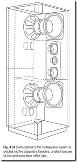
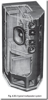
Since multispeaker systems, Figs. 4.34 and 4.35, are composed of combinations of special purpose speakers, the multispeaker system as a whole is a very efficient system. Multispeaker systems have the following advantages :
(i) Multispeaker systems have reserve power handling capacity necessary for high program bursts.
(ii) Multispeaker systems reduce intermodulation distortion.
(iii) Multispeaker systems may be balanced one against the other by means of volume controls to give that particular feeling of concert hall reality that most pleases the listener.
(iv) A smooth overall response may be obtained from multispeaker systems.
(v) Multispeaker systems have compatible ‘roll off’ or ‘cut off’ characteristics; speaker ranges overlap.
(vi) Multispeaker systems provide flexibility of performance.
CROSSOVER NETWORKS
In multispeaker systems, in which specialised speakers are used for different frequency hands, it is necessary and desirable to segregate different bands of frequencies into the respective speakers designed to handle them. This segregation of the various bands of acoustic energy ensures optimum utilisation of audio power resulting in better overall performance of the system.
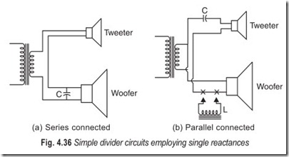
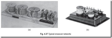
The simplest type of network consists merely of a single capacitor, as illustrated in Fig. 4.36 (a). The fact that the reactance of a capacitor is inversely proportional to frequency is employed to distribute the audio signal. The tweeter and woofer voice coils are connected in series and a capacitor is connected across the woofer. The value of capacitance is made such that frequencies above the range of the woofer, the reactance of C becomes so low that it shunts the woofer, which acts as a bypass capacitor.
Low-frequency components can be kept out of the tweeter if a parallel connection of voice coil is used with capacitor in series with the tweeter circuit, as shown in Fig. 4.36 (b).
Inductances can be used along with capacitors to make the crossover network more complete. For example, in Fig. 4.36 (b) the inductance ( L) can be connected in series with the woofer leads as shown. The inductance, the reactance of which increases with frequency, chokes the high frequency components out of the woofer, and the capacitor (C) blocks low frequency components out of the tweeter. The values of C and L must be such that the reactance in each case is a little lower than the voice-coil impedance in the frequency range to be attenuated.
Although the crossover range should not be too narrow, simple reactance circuits are ordinarily too broad in the change over region. A combination of low pass filter (for the woofer) and a high-pass filter (for the tweeter) is usually employed. With this type of circuit, much more rapid attenuation can be made near the crossover frequency than is possible with simple capacitor and inductor arrangements.
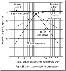
Attenuation of 12 dB per octave is considered proper in most applications. Gradual crossover arrangements attenuate at about 6 dB per octave. Filters with sharper cut off than this can be constructed by the use of additional components, but power losses in the filter become excessive and the additional sharpness is not necessary anyway.
A typical crossover network response graph is shown in Fig. 4.38. The curve of woofer output crosses the curve of tweeter output response at the crossover frequency. This intersection is at the 3 dB or half- power level, at the crossover frequency, half the output power is being fed to each unit. The individual response characteristics of the woofer and tweeter must overlap substantially.
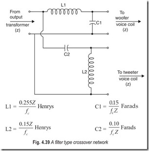
One of the most popular types of crossover networks is shown in Fig. 4.39 alongwith the formulas for calculating the values required for anycrossover frequency fc and speaker impedance Z.
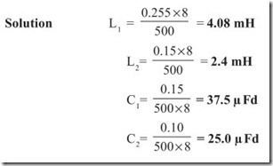
Example 4.1 Find the component values for fc = 500 Hz and Z = 8 ohms.
IMPEDANCE MATCHING
It will be useful to give a simple recapitulation of transformer theory. A transformer represents a straight forward application of the phenomenon known as electromagnetic induction, whereby any change in the magnetic flux linking an electric circuit is accompanied by an induced electromotive force in that circuit. The value of this induced voltage will, at any instant, be proportional to the rate of change of the flux, while its direction will always be such as to oppose the change producing it. The change of linkages may be produced by movement of the electric circuit with respect to a magnetic field which is constant, as in a dynamo, or by varying the current in a stationary electric circuit. When the induced emf produced in one circuit is due to a current varying in an adjacent circuit, as in a transformer, it is said to be due to the mutual inductance between the two circuits. The emf induced in a circuit by a varying current flowing in the circuit itself is said to be due to the self-inductance of the circuit. The inductance of a conductor can be increased by winding it in a coil and further increased by winding the coil on a core of ferromagnetic material.
In general, a transformer consists of two insulated coils of wire so associated that the magnetic flux due to a current in one coil is effectively linked with the turns of the other coil. The coils are normally wound on a core of ferromagnetic material which greatly increases the magnetic effect of the current. Usually one of the windings, the one to which the input is connected, is called the primary and the other is called the secondary. In some instances additional windings may be provided to give alternative outputs.
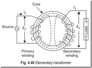
An elementary transformer corresponding to the form used by Faraday in his original experiments is shown diagrammatically in Fig. 4.40. An alternating current, Ip , flowing in the primary winding will cause analternating magnetic flux, indicated by the dotted lines, to circulate in the ring core. In doing so, this alternating magnetic flux will link with the turns of both windings and induce, assuming an ideal transformer, an emf, E, in each turn, proportional from instant to instant to the rate of change of current in the primary. This induced voltage will act in such a direction so as to tend to oppose the change of flux and in the primary winding it will take the form of a back emf. If Np is the number of turns in the primary winding the total back emf will be equal to NpE and neglecting any losses in the transformer this will be equal to the impressed emf Ep . In other words, stability is established when the primary current has a value equal to that required to induce a back emf, opposite to the applied emf.
Similarly, if Ns is the number of turns in the secondary winding, the total emf,Es, induced in the secondary winding is equal to NsE. We thus have
Ep= NpE …(4.1)
and Es = NsE …(4.2)
Again assuming an ideal transformer having no losses, the power in the secondary circuit will be the same as that at the input to the primary winding; thus we have.
Ip Ep = IsEs …(4.4)
We therefore have the following relationships :
Thus the ratio of the primary and secondary voltages is equal to the turns ratio, while the ratio of the primary and secondary currents is the inverse of the turns ratio. The transformer, therefore, provides a ready means of converting an alternating supply voltage to another value, either higher or lower, depending on the requirements, and this constitutes one of its most common uses. Where ac mains are used to provide power supplies to telecommunication equipment, transformers also serve the purpose of isolating the equipment from direct connection to the mains, both on grounds of safety and to prevent unwanted earth potentials reaching the equipment.
Apart from their uses in connection with power supplies, transformers find very many uses in telecommunication circuits. In signalling and switching circuits they may be used for isolating two parts of a connection for direct current while permitting the transmission of speech currents between the two parts. They may also be used to connect an earthed circuit to one which has both sides balanced with respect to earth.
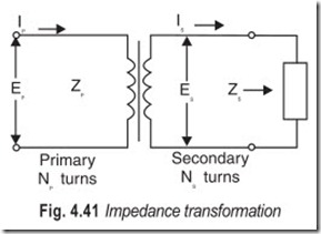
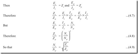
A further use of a transformer is for impedance matching. This is to allow a low impedance circuit to be connected to a high impedance circuit or vice versa without loss of power. In this case the turns ratio required is equal to the square root of the ratio of the impedances to be matched as can be seen from the following :
Let Zp = Impedance as measured at terminals of primary winding (Fig. 4.41)
Zs = Impedance of circuit connected to secondary winding
EXERCISES
Descriptive Questions
1. Explain the difference between a microphone and a loudspeaker.
2. What are the requirements of an ideal loudspeaker?
3. What are the different types of loudspeaker? Explain the working of any one of them with the help of a neat diagram.
4. Discuss the limitations of ceramic and electrostatic speakers. What are their fields of application?
5. Draw the equivalent circuit of a dynamic loudspeaker and explain the significance of each component.
6. Explain the following terms :
(a) Compliance
(b) Inertance
(c) Reflected impedance
7. What type of voice coil and voice coil suspension will you use in
(a) Woofers
(b) Tweeters
8. Explain in detail the working of a permanent magnet loudspeaker.
9. What is the difference between a cone-type tweeter and a dome-type tweeter?
10. Explain why the efficiency of an indirect radiating loudspeaker is greater than that of a direct radiating loudspeaker?
11. Discuss the relative merits and demerits of horn type and cone type speakers.
12. Explain the working of either horn type or cone type loudspeaker with the help of a neat diagram.
13. Why multispeaker systems are required?
14. Explain the difference between a subwoofer, woofer, mid-range speaker, supertweeter and tweeter.
15. What are the advantages of multispeaker system?
16. Explain the working of a simple crossover network.
17. With the help of a block diagram explain a hi-fi system.
18. Explain the following briefly.
(a) Presence (b) Distortion
(c) Input devices (d) Amplifier system
19. What is significance of a transformer in impedance matching?
20. How will you match a low impedance to a high impedance? Give a practical example.
Multiple Choice Questions
1. A loudspeaker converts
(a) electrical energy to mechanical energy
(b) acoustic energy to electrical energy
(c) mechanical energy to electrical energy
(d) electrical energy to acoustic energy
2. The input impedance of a crystal loudspeaker is
(a) resistive (b) inductive
(c) capacitive (d) a combination of (a) and (b)
3. Crystal speakers are used in
(a) low frequencies (b) high frequencies
(c) mid frequencies (d) both (c) and (d)
4. Electrostatic speakers need a
(a) dc polarising voltage (b) ac polarising voltage
(c) either (a) or (b) (d) neither (a) nor (b)
5. The dc bias (polarising voltage) in electrostatic speakers is of the order of (a) 500 to 1000 V (b) 1100 to 1500 V
(c) 1000 to 1200 V (d) 500 to 1200 V
6. High class sound systems use electrostatics to reproduce
(a) low frequencies (b) mid frequencies
(c) high frequencies (d) both (a) and (b)
7. High quality dynamic speakers use diaphragms composed of
(a) paper (b) titanium
(c) aluminium (d) none of the above
8. Woofers are speakers designed to reproduce
(a) bass (b) treble
(c) neither (a) nor (b) (d) either (a) or (b)
9. Tweeters are speakers designed to reproduce
(a) low frequencies (b) high frequencies
(c) mid frequencies (d) both (a) and (c)
10. The smallest diaphragm for any half-way decent woofer is (a) 4″ (b) 6″
(c) 8″ (d) 12″
11. High resonant frequencies are obtained with
(a) light weight (b) stiff suspension
(c) loose suspension (d) heavy weight
12. A horn-loaded unit
(a) increases the acoustic output
(b) decreases the acoustic output
(c) multiplies the acoustic output
(d) none of these
Fill in the Blanks
1. The principle of operation of a loudspeaker is the of that of a microphone.
2. Crystals have been known to under stresses.
3. To overcome frequency doubling we the speakers.
4. The voice coil is free to move but not vertically or laterally.
5. The stronger the magnet, the the speaker.
6. magnets have several advantages over those made of metal.
7. The is that part of the speaker which does the talking.
8. Mechanical inductance is called .
9. Mechanical is called compliance.
10. Undesired sharpness of the resonant peak can be lessened by .
11. Directivity normally varies considerably with .
12. The does acoustically what the cone does mechanically.
ANSWERS
Multiple Choice Questions
|
1. (d) 2. (c) |
3. (b) |
4. (a) |
5. (c) |
6. (c) |
|
7. (a), (b) & (c) 8. (a) |
9. (b) |
10. (c) |
11. (a) & (b) |
12. (a) |
Fill in the Blanks
|
1. reverse |
2. vibrate |
3. polarise |
|
4. back & forth |
5. better |
6. ceramic |
|
7. voice coil 10. damping |
8. inertance 11. frequency |
9. capacitance 12. horn |
