VARIABLE-VOLTAGE CONTROL
The variation in speed obtainable by field control on the conventional de motor will not, in most cases, exceed 4 to 1 due to the sparking difficul ties experienced with very weak fields. Although the range may be in creased by inserting resistance in series with the armature, this can be done only at the expense of efficiency and speed regulation.
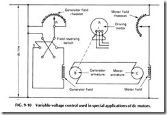
With constant voltage applied to the field, the speed of a de motor varies directly with the armature voltage; therefore, such a motor may be steplessly varied from zero to maximum operating speed by increasing the voltage applied to its armature. The diagram in Fig. 9-10 shows the arrangement of machines and the connections used in one type of variable-voltage control designed to change speed and reverse rotation. The constant-speed de generator (B) is usually driven by an ac motor (A), and its voltage is controlled by means of a rheostat (R). Note that the fields of both generator and driving motor are energized from a separate de supply or by an auxiliary exciter driven off the generator shaft, caus ing the strength of the motor field to be held constant, while the genera tor field may be varied widely by rheostatR.
With the system in operation, generator B is driven at a constant speed by prime mover A. Voltage from B is applied to the de motor (C) which is connected to the machine to be driven. By proper manipulation of rheostat R and field reversing switch S, the de motor may be gradually started, brought up to and held at any speed, or reversed. As all of these changes may be accomplished without breaking lines to the main motor the control mechanism is small, relatively inexpensive, and less likely to give trouble than the equipment designed for heavier currents.
The advantage of this system is the flexibility of the control and also the complete elimination of resistor losses, the relatively great range over which the speed can be varied, the excellent speed regulation on each set ting, and the fact that changing the armature voltage does not diminish the maximum torque which the motor is capable of exerting, since the field flux is constant.
By means of the arrangement shown in Fig. 9-10, speed ranges of 20 to 1-as compared to 4 to 1 for shunt field control- may be secured.
Speeds above the rated normal full-load speed may be obtained by insert ing resistance in the motor shunt field. This represents a modification of the variable-voltage control method which was originally designed for the operation of constant-torque loads up to the rated normal full-load speed.
As three machines are usually required, this type of speed control finds application only where great variations in speed and unusually smooth control are desired. Steel mill tools, electric shovels, passenger elevators, machine tools, turntables, large ventilating fans, and similar equipment represent the type of machinery to which this method of speed control has been applied.
OVERLOAD RELAYS
To protect the motor and related circuits from accidental or prolonged overloads, either the starter or the motor should be equipped with auto matic devices that will open the circuit should an overload exist. This pro tection can be provided by fuses, circuit breakers, or overload relays.
Overcurrent protection must be provided in the line of every motor circuit, but additional protection should be provided in the form of mag netic overload relays. These are used in both manual and automatic starters.
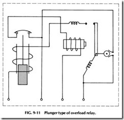
Figure 9-11 shows a plunger type of overload relay. When the cur rent through the coil reaches the value set by the adjustable screw, the plunger is drawn up and opens two contacts. This type of relay can be used on both the manual and automatic controller.
Most overload relays used on modern starters are thermally oper ated and usually consist of two strips of metal having different degrees of thermal expansion which are welded together. If this bimetallic strip is heated, it will deflect sufficiently to trip two normally closed contacts, which in turn will open-circuit the holding coil of a magnetic contactor, causing the main contacts to open. An advantage of this protective device is that it provides a time delay which prevents the circuit from be ing opened by momentary high starting currents and short overloads. At the same time it protects the motor from prolonged overloading.

