Output contacts
Normally Open contact terminals 5 and 6. When CR1 is energized, the contact will close and open the dampers.
Normally Open contact terminals 7 and 8. When CR1 is energized, the contact will close and close the digital input to DGH1, which will communicate to the PLC over the RS-232 network, and the PLC can react and run the required program.
RS-485 Introduction and Specifications
RS-485 is the most versatile communication standard in the stan- dard series defined by the EIA. RS-485 connects data terminal equipment (DTE)/remote terminal unit (RTU) directly without the need for modems and connects several DTEs/RTUs in a network structure. It has the ability to communicate over long distances and virtually unlimited nodes with the use of repeaters. It has the ability to communicate at faster speeds. This is why RS-485 is currently the most widely used communication interface in data acquisition and control applications where multiple nodes communicate with one another.
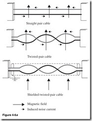
The signal is measured from signal + to signal – communication lines; this differential signal method results in longer distances and higher bit rates. One of the most significant problems with RS-232 is the lack of immunity for noise on the communication lines. The trans- mitter and receiver compare the voltages of the data and handshake lines with signal ground common zero line. Changes in the ground level can have disastrous effects. Therefore the level of the RS-232 interface is relatively high at ±3 V. Noise is easily induced and limits both the maximum distance and communication speed. With RS-485, on the other hand, there is no such thing as a common zero as a signal reference. A difference of several volts between the ground level of the RS-485 transmitter and receiver does not cause any problems. The RS-485 signals are floating, and each signal is transmitted over a signal + line and a signal – line. The RS-485 receiver compares the voltage difference between both lines, instead of the absolute voltage level on a signal line. This works well and prevents the existence of ground loops, a common source of communication problems. The best results are achieved if the signal + and signal – communication lines are twisted and separately shielded. Figure 4-6a explains this concept.
Figure 4-6a shows the effect of a magnetic field, which can generate noise on the communication lines.
Straight pair cable allows the magnetic field to induce noise spikes on the communication lines.
Twisted-pair cable has induced noise in opposing directions, thereby canceling the noise.
Shielded twisted-pair cable is virtually noise-free. The shield blocks the magnetic field from inducing noise in the communication lines. The only way that noise can affect the communication lines is at the stripped end. This is why the stripped end should be as short as possible.
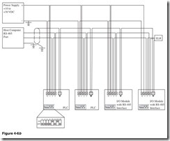
Figure 4-6b is a wiring diagram of an RS-485 multipoint network. Shielded cable is used to reduce or eliminate noise. When terminat- ing the wire, make the exposed (stripped) end of the wire as short as possible, and keep it away from power conductors to minimize the introduction of noise. This diagram is based on the specification for the DGH Corporation modules. Check the job specification to ensure proper wiring of the modules.
1. Host computer with RS-485 serial port. This will usually be a 9-pin connector; see Fig. 4-4a for pin out.
2. Green signal – is looped through the devices and connected on the signal – terminal (G). This is not connected to earth or frame ground. Make sure that the connection is electrically and mechanically secure. If the wire should come loose, the network from this point forward will be lost.
3. Orange signal + is looped through the devices and connected on the signal + terminal (Y). Make sure that the connection is electrically and mechanically secure. If the wire should come loose, the network from this point forward will be lost.
4. Red power positive + is looped through the devices and connected on the signal + terminal (R). Make sure that the connection is electri- cally and mechanically secure. If the wire should come loose, the network from this point forward will be lost.
5. Black power negative – is looped through the devices and connected on the signal + terminal (B). Make sure that the connection is elec- trically and mechanically secure. If the wire should come loose, the network from this point forward will be lost.
6. Blue is the shield that is grounded in the panel to the earth or frame ground. The shield is only grounded at one end in the panel. This is to prevent a ground loop and to eliminate noise. I like to use heat shrink tubing to insulate the ground. If this is not possible, then tape the shield ground so that it does not short or touch the ground. Use the good tape—not the 12 rolls for a dollar stuff. I like to terminate the wire with a crimp-type wire nut to ensure that the connection will not vibrate loose.
Module address Each module in the RS-485 multipoint network must have a unique address. This is usually done with a dip or rotary switch. Figure 4-6b is a dip switch, which sets the module address. Care should be taken to set the module to the proper address or the module will not be accessible from the network. Setting two modules to the same address will disable both modules. The method used to set the address is called Binary Coded Decimal (BCD). Each switch is assigned a value of 1, 2, 4, 8, 16, 32, 64, or 128. You can set a combination of these numbers to any address from 1 to 256; for example, in Fig. 4-6b the switches are set to ON and the values the modules are set to are added—16 + 64 = 80, 2 + 16 = 18, 8 + 32 = 40, and 2 + 4 = 6. Typically the addresses are not random. A wiring diagram, print, or module printout will have a specific address to use to set the correct address for each module. Care should be taken to read the switch. The values can run from right to left or left to right. The ON setting can be on the top or the bottom of the switch.
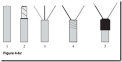
Figure 4-6c is a method for terminating a shielded twisted-pair cable.
1. Shielded twisted-pair cable.
2. Strip the cable, keeping the stripped wire as short as possible, being careful not to nick the wires and expose the shield. Keep the stripped wire away from power conductors to minimize noise.
3. Remove the shield and separate the wires. In Fig. 4-6c the light gray wire is the shield, the black wire is the R (receive data), and the dark gray wire is the T (transmit data).
4. Twist the shield back around the wire to keep it from grounding or shorting.
5. Insulate the shield. I like to use heat shrink tubing. If that is not possible, then wrap tape around the shield, insulating the shield. If you use tape, then use the good tape—it is important that this does not come loose with heat or humidity.
Figure 4-6d is a method for terminating a shielded twisted-pair cable for an RS-485 multipoint network.
1. Shielded twisted-pair cables.
2. Strip each of the cables, keeping the stripped wire as short as pos- sible, being careful not to nick the wires and expose the shield. Keep the stripped wire away from power conductors to minimize noise.
3. Remove the shield and separate the wires. In Fig. 4-6d the light gray wire is the shield, the black wire is the R (receive data), and the dark gray wire is the T (transmit data).
4. Join the cables and twist the shield together.
Twist the shields back around the wire to keep it from grounding or shorting.
5. Insulate the shield. I like to use heat shrink tubing. If that is not possible, then wrap tape around the shield, insulating the shield. If you use tape, then use good tape—it is important that this does not come loose with heat or humidity.
6. Twist the stripped end of the wires and connect them to the connector.
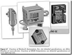
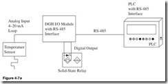
Figure 4-7 is an Allen Bradley 837E temperature sensor with 4- to 20-mA output; an Allen Bradley MicroLogix 1100 PLC with RS-232, RS-485, and Ethernet; an Allen Bradley 700SE solid-state relay; and a DGH Corporation D1112 RS-485 I/O module with analog input and digital output. Using the DGH Corporation modules, you can have up to 124 modules on one RS-485 communication line. This will require repeaters every 32 modules. This may change from manufacturer to manufacturer; check the specification of the modules to determine the maximum number and configuration per line.
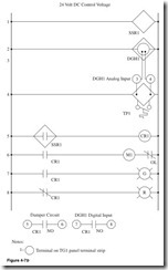
Shown in Fig. 4-7b:
Line 1 Power for SSR1.
Line 2 Power for DGH1.
Line 3 Analog input of 4 to 20 mA to DGH1.
Line 4 Power to temperature sensor. Output from sensor of 4 to 20 mA to input of DGH1.
Line 5 Normally Open contact SSR1, CR1 coil. When the tempera- ture sensor is in the preset range, the DGH1 module outputs a signal to the digital output, which energizes the SSR1, closes the contact, and holds it closed until the temperature is outside of the preset range. This energizes control relay CR1. DGH1 will communicate the tem- perature to the PLC over the RS-485 network and the PLC can react and run the required program.
Line 6 Normally Open contact CR1, coil motor starter M1, Normally Closed overload contact of M1. When CR1 is energized, the motor will start the blower motor.
Line 7 Normally Open contact CR1, green pilot light. When CR1 is energized, the green pilot light will be illuminated.
Line 8 Normally Closed contact CR1. The red pilot light will be illuminated until CR1 is energized.
Output contacts
Normally Open contact terminals 5 and 6. When CR1 is energized, the contact will close and open the dampers.
Normally Open contact terminals 7 and 8. When CR1 is energized, the contact will close and close the digital input to DGH1, which will communicate to the PLC over the RS-485 network, and the PLC can react and run the required program.
Modbus Introduction and Specifications
Modbus was introduced in 1979 when PLC manufacturer Modicon, now a brand of Schneider Electric, published the Modbus communication interface for a multipoint network based on a master/client architecture. Simply put, it is a language that devices (nodes) use to communicate with the host system. The original Modbus protocol ran on RS-232, but most later Modbus implementations used RS-485 and Ethernet TCP/IP because it allowed longer distances, higher speeds, and a true multipoint network. In a short time vendors implemented the Modbus messaging system in their devices, and Modbus became the standard for industrial communication networks.
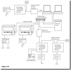
The Modbus standard has flexibility and is easy to implement. Not only are intelligent devices such as microcontrollers, PLCs, etc., able to communicate with Modbus, but also many intelligent sensors and equipment are equipped with a Modbus-compatible interface to send their data to host systems. With the use of a PLC like Allen Bradley Micrologix 1100 or converters like the units offered by DGH Corporation, it is possible to communicate the Modbus Protocol from one topology to another. This allows a large number of nodes to communicate on RS-485 and connect to the host computers using an Ethernet TCP/IP network. Modbus is a language that is used for the communications of data from node to node and node to host system across many network topologies. It is not a hardware module, topology, or wiring method.
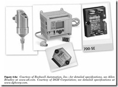
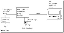
Figure 4-8a is an Allen Bradley 837E temperature sensor with 4- to 20-mA output; an Allen Bradley MicroLogix 1100 PLC with RS-232, RS-485, and Ethernet TCP/IP; an Allen Bradley 700SE solid-state relay; and a DGH Corporation D1112M RS-485 I/O module with analog input and digital output. Using the DGH Corporation modules, you can have up to 247 modules on one RS-485 communication line. This will require repeaters every 32 modules. This may change from manufacturer to manufacturer; check the specification of the modules to determine the maximum number and configuration per line.
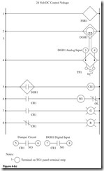
Shown in Fig. 4-8c:
Line 1 Power for SSR1.
Line 2 Power for DGH1.
Line 3 Analog input of 4 to 20 mA to DGH1.
Line 4 Power to temperature sensor. Output from sensor of 4 to 20 mA to input of DGH1.
Line 5 Normally Open contact SSR1, CR1 coil. When the tempera- ture sensor is in the preset range, the DGH1 module outputs a signal to the digital output which energizes the SSR1, closes the contact, and holds it closed until the temperature is outside of the preset range. This energizes control relay CR1. DGH1 will communicate the tem- perature to the PLC over the RS-485 network and the PLC can react and run the required program.
Line 6 Normally Open contact CR1, coil motor starter M1, Normally Closed overload contact of M1. When CR1 is energized, the motor will start the blower motor.
Line 7 Normally Open contact CR1, green pilot light. When CR1 is energized, the green pilot light will be illuminated.
Line 8 Normally Closed contact CR1, red pilot light will be illumi- nated until CR1 is energized.

