Synchronous Machines Notes
Introduction
Synchronous machines are principally used as alternating current generators. They supply the electric power used by all sectors of modern society. Synchronous machine is an important electromechanical energy converter. Synchronous generators usually operate in parallel forming a large power system supplying electrical power to consumers or loads. For these applications the synchronous generators are built in large units, their rating ranging form tens to hundreds of Megawatts. These synchronous machines can also be run as synchronous motors.
Synchronous machines are AC machines that have a field circuit supplied by an external DC source. Synchronous machines are having two major parts namely stationary part stator and a rotating field system called rotor.
In a synchronous generator, a DC current is applied to the rotor winding producing a rotor magnetic field. The rotor is then driven by external means producing a rotating magnetic field, which induces a 3-phase voltage within the stator winding.
Field windings are the windings producing the main magnetic field (rotor windings for synchronous machines); armature windings are the windings where the main voltage is induced (stator windings for synchronous machines).
Types of synchronous machines
According to the arrangement of armature and field winding, the synchronous machines are classified as rotating armature type or rotating field type.
In rotating armature type the armature winding is on the rotor and the field winding is on the stator. The generated emf or current is brought to the load via the slip rings. These type of generators are built only in small units.
In case of rotating field type generators field windings are on the rotor and the armature windings are on the stator. Here the field current is supplied through a pair of slip rings and the induced emf or current is supplied to the load via the stationary terminals.
Based on the type of the prime movers employed the synchronous generators are classified as
1. Hydrogenerators : The generators which are driven by hydraulic turbines are called hydrogenerators. These are run at lower speeds less than 1000 rpm.
2. Turbogenerators: These are the generators driven by steam turbines. These generators are run at very high speed of 1500rpm or above.
3. Engine driven Generators: These are driven by IC engines. These are run at aspeed less than 1500 rpm.
Hence the prime movers for the synchronous generators are Hydraulic turbines, Steam turbines or IC engines.
Hydraulic Turbines: Pelton wheel Turbines: Water head 400 m and above Francis turbines: Water heads up to 380 m
Keplan Turbines: Water heads up to 50 m
Steam turbines: The synchronous generators run by steam turbines are called turbogenerators or turbo alternators. Steam turbines are to be run at very high speed to get higher efficiency and hence these types of generators are run at higher speeds.
Diesel Engines: IC engines are used as prime movers for very small rated generators.
Construction of synchronous machines
1. Salient pole Machines: These type of machines have salient pole or projecting poles with concentrated field windings. This type of construction is for the machines which are driven by hydraulic turbines or Diesel engines.
2. Nonsalient pole or Cylindrical rotor or Round rotor Machines: These machines are having cylindrical smooth rotor construction with distributed field winding in slots. This type of rotor construction is employed for the machine driven by steam turbines.
1. Construction of Hydro-generators: These types of machines are constructed based on the water head available and hence these machines are low speed machines. These machines are constructed based on the mechanical consideration. For the given frequency the low speed demands large number of poles and consequently large diameter. The machine should be so connected such that it permits the machine to be transported to the site. It is a normal to practice to design the rotor to withstand the centrifugal force and stress produced at twice the normal operating speed.
Stator core:
The stator is the outer stationary part of the machine, which consists of
• The outer cylindrical frame called yoke, which is made either of welded sheet steel, cast iron.
• The magnetic path, which comprises a set of slotted steel laminations called stator core pressed into the cylindrical space inside the outer frame. The magnetic path is laminated to reduce eddy currents, reducing losses and heating. CRGO laminations of 0.5 mm thickness are used to reduce the iron losses.
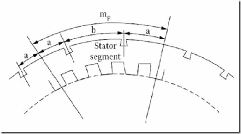
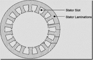
A set of insulated electrical windings are placed inside the slots of the laminated stator. The cross- sectional area of these windings must be large enough for the power rating of the machine. For a 3- phase generator, 3 sets of windings are required, one for each phase connected in star. Fig. 1 shows one stator lamination of a synchronous generator. In case of generators where the diameter is too large stator lamination can not be punched in on circular piece. In such cases the laminations are punched in segments. A number of segments are assembled together to form one circular laminations. All the laminations are insulated from each other by a thin layer of varnish.
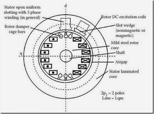
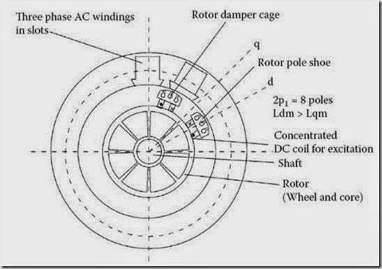
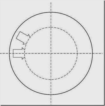
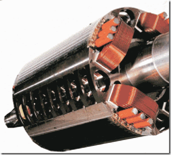
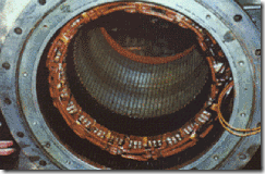
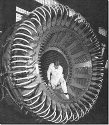
Details of construction of stator are shown in Figs 1 – 5
Figure.1. Nonsalient pole generator
Figure.2. Salient pole generator
Figure.3.
Figure.4.
(a)
(b)
Fig. 5. Stator lamination (a) Full Lamination (b) Segment of a lamination
Fig 6. (a) Stator and (b) rotor of a salient pole alternator
Fig 7. (a) Stator of a salient pole alternator
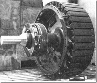
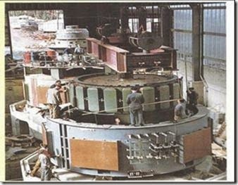 Fig 8. Rotor of a salient pole alternator
Rotor of water wheel generator consists of salient poles. Poles are built with thin silicon steel laminations of 0.5mm to 0.8 mm thickness to reduce eddy current laminations. The laminations are clamped by heavy end plates and secured by studs or rivets. For low speed rotors poles have the bolted on construction for the machines with little higher peripheral speed poles have dove tailed construction as shown in Figs. Generally rectangular or round pole constructions are used for such type of alternators. However the round poles have the advantages over rectangular poles.
Generators driven by water wheel turbines are of either horizontal or vertical shaft type. Generators with fairly higher speeds are built with horizontal shaft and the generators with higher power ratings and low speeds are built with vertical shaft design. Vertical shaft generators are of two types of designs (i) Umbrella type where in the bearing is mounted below the rotor. (ii) Suspended type where in the bearing is mounted above the rotor.
In case of turbo alternator the rotors are manufactured form solid steel forging. The rotor is slotted to accommodate the field winding. Normally two third of the rotor periphery is slotted to accommodate the winding and the remaining one third unslotted portion acts as the pole. Rectangular slots with tapering teeth are milled in the rotor. Generally rectangular aluminum or copper strips are employed for filed windings. The field windings and the overhangs of the field windings are secured in place by steel retaining rings to protect against high centrifugal forces. Hard composition insulation materials are used in the slots which can with stand high forces, stresses and temperatures. Perfect balancing of the rotor is done for such type of rotors.
Damper windings are provided in the pole faces of salient pole alternators. Damper windings are nothing but the copper or aluminum bars housed in the slots of the pole faces. The ends of the damper bars are short circuited at the ends by short circuiting rings similar to end rings as in the case of squirrel cage rotors. These damper windings are serving the function of providing mechanical balance; provide damping effect, reduce the effect of over voltages and damp out hunting in case of alternators. In case of synchronous motors they act as rotor bars and help in self starting of the motor.
Relative dimensions of Turbo and water wheel alternators:
Turbo alternators are normally designed with two poles with a speed of 3000 rpm for a 50 Hz frequency. Hence peripheral speed is very high. As the diameter is proportional to the peripheral speed, the diameter of the high speed machines has to be kept low. For a given volume of the machine when the diameter is kept low the axial length of the machine increases. Hence a turbo alternator will have small diameter and large axial length.
However in case of water wheel generators the speed will be low and hence number of poles required will be large. This will indirectly increase the diameter of the machine. Hence for a given volume of the machine the length of the machine reduces. Hence the water wheel generators will have large diameter and small axial length in contrast to turbo alternators.
Relation between Speed and Frequency: In the previous course on induction motors it is established that the relation between speed and frequency and number of poles is given by
Frequency f = P x N /120 Hz
Windings in Alternators: In case of three phase alternators the following types of windings are employed.
(i) Lap winding,
(ii) wave winding and
(iii) mush winding.
Based on pitch of the coil
(i) full pitched
(ii) short pitched windings
Based on number of layers
(i) Single layer
(ii) Double layer
Above figures show the details of full pitched and short pitched coils.
The above figures show the details of lap and wave windings for one phase
EMF Equation of an alternator:
Consider the following
Φ = flux per pole in wb P = Number of poles
Ns = Synchronous speed in rpm
f = frequency of induced emf in Hz
Z = total number of stator conductors
Zph = conductors per phase connected in series Tph = Number of turns per phase
Assuming concentrated winding, considering one conductor placed in a slot According to Faradays Law electromagnetic induction,
The average value of emf induced per conductor in one revolution eavg = d<l/dt eavg = Change of Flux in one revolution/ Time taken for one revolution
Change of Flux in one revolution = p x <l
Time taken for one revolution = 60/Ns seconds
This is the general emf equation for the machine having concentrated and full pitched winding.
In practice, alternators will have short pitched winding and hence coil span will not be 1800, but on or two slots short than the full pitch.
Pitch Factor:
As shown in the above figure, consider the coil short pitched by an angle α, called chording angle. When the coils are full pitched the emf induced in each coil side will be equal in magnitude and in phase with each other. Hence the resultant emf induced in the coil will be sum of the emf induced. Hence Ec = E1 + E2 = 2E for full pitched coils,
Hence total emf = algebraic sum of the emfs = vector sum of emfs as shown in figure below
Fig 20
When the coils are shot pitched by an angle α, the emf induced in each coil side will be equal in magnitude but will be out of phase by an angle equal to chording angle. Hence the resultant emf is equal to the vector sum of the emfs as shown in figure below.
Hence the resultant coil emf is given by Ec = 2E1 cos α/2 = 2E cos α/2 volts.
Hence the resultant emf in the short pitched coils is dependant on chording angle α. Now the factor by which the emf induced in a short pitched coil gets reduced is called pitch factor and defined as the ratio of emf induced in a short pitched coil to emf induced in a full pitched coil.
Pitch factor Kp= emf induced in a short pitched coil/ emf induced in a full pitched coil
= (2E cos α/2 )/ 2E
Kp = cos α/2
where α is called chording angle.
Distribution Factor: Even though we assumed concentrated winding in deriving emf equation, in practice an attempt is made to distribute the winding in all the slots coming under a pole. Such a winding is called distributed winding.
In concentrated winding the emf induced in all the coil sides will be same in magnitude and in phase with each other. In case of distributed winding the magnitude of emf will be same but the emfs induced in each coil side will not be in phase with each other as they are distributed in the slots under a pole. Hence the total emf will not be same as that in concentrated winding but will be equal to the vector sum of the emfs induced. Hence it will be less than that in the concentrated winding. Now the factor by which the emf induced in a distributed winding gets reduced is called distribution factor and defined as the ratio of emf induced in a distributed winding to emf induced in a concentrated winding.
Distribution factor Kd = emf induced in a distributed winding/ emf induced in a concentrated winding
= vector sum of the emf/ arithmetic sum of the emf
Let
E = emf induced per coil side
m = number of slots per pole per phase, n = number of slots per pole
β = slot angle = 180/n
The emf induced in concentrated winding with m slots per pole per phase = mE volts.
In practical machines the windings will be generally short pitched and distributed over the periphery of the machine. Hence in deducing the emf equation both pitch factor and distribution factor has to be considered.
Harmonics: When the uniformly sinusoidally distributed air gap flux is cut by either the stationary or rotating armature sinusoidal emf is induced in the alternator. Hence the nature of the waveform of induced emf and current is sinusoidal. But when the alternator is loaded waveform will not continue to
be sinusoidal or becomes nonsinusoidal. Such nonsinusoidal wave form is called complex wave form. By using Fourier series representation it is possible to represent complex nonsinusoidal waveform in terms of series of sinusoidal components called harmonics, whose frequencies are integral multiples of fundamental wave. The fundamental wave form is one which is having the frequency same as that of complex wave.
The waveform, which is of the frequency twice that of the fundamental is called second harmonic. The one which is having the frequency three times that of the fundamental is called third harmonic and so on. These harmonic components can be represented as follows.
Slot Harmonics: As the armature or stator of an alternator is slotted, some harmonics are induced into the emf which is called slot harmonics. The presence of slot in the stator makes the air gap reluctance at the surface of the stator non uniform. Since in case of alternators the poles are moving or there is a relative motion between the stator and rotor, the slots and the teeth alternately occupy any point in the air gap. Due to this the reluctance or the air gap will be continuously varying. Due to this variation of reluctance ripples will be formed in the air gap between the rotor and stator slots and teeth. This ripple formed in the air gap will induce ripple emf called slot harmonics.
Minimization of Harmonics: To minimize the harmonics in the induced waveforms following methods are employed:
1. Distribution of stator winding.
2. Short Chording
3. Fractional slot winding
4. Skewing
5. Larger air gap length.
Effect of Harmonics on induced emf:
The harmonics will affect both pitch factor and distribution factor and hence the induced emf. In a well designed alternator the air gap flux density distribution will be symmetrical and hence can be represented in Fourier series as follows.
Numerical Problems:
1. A 3Φ, 50 Hz, star connected salient pole alternator has 216 slots with 5 conductors per slot. All the conductors of each phase are connected in series; the winding is distributed and full pitched. The flux per pole is 30 mwb and the alternator runs at 250 rpm. Determine the phase and line voltages of emf induced.
2. A 3Φ, 16 pole, star connected salient pole alternator has 144 slots with 10 conductors per slot.
The alternator is run at 375 rpm. The terminal voltage of the generator found to be 2.657 kV. Dteremine the frequency of the induced emf and the flux per pole.
Soln: Ns = 375 rpm, p =16, slots = 144, Total no. of conductors = 144 x 10 = 1440 EL = 2.657 kV,
3. A 4 pole, 3 phase, 50 Hz, star connected alternator has 60 slots with 4 conductors per slot. The coils are short pitched by 3 slots. If the phase spread is 600, find the line voltage induced for a flux per pole of 0.943 wb.
4. In a 3 phase star connected alternator, there are 2 coil sides per slot and 16 turns per coil. The stator has 288 slots. When run at 250 rpm the line voltage is 6600 volts at 50 Hz. The coils are shot pitched by 2 slots. Calculate the flux per pole.
5. A 10 pole, 600 rpm, 50Hz, alternator has the following sinusoidal flux density distribution.
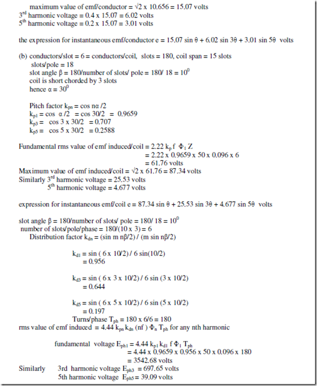
B = sin θ + 0.4 sin 3θ + 0.2 sin 5θ wb/m2. The alternator has 180 slots with 2 layer 3 turn coils with a coil span of 15 slots. The coils are connected in 600 groups. If the armature diameter is 1.2 m and core length is 0.4 m, calculate (a) the expression for instantaneous emf/conductor (b) the expression for instantaneous emf/coil (c) the phase and line voltages if the machine is star connected.
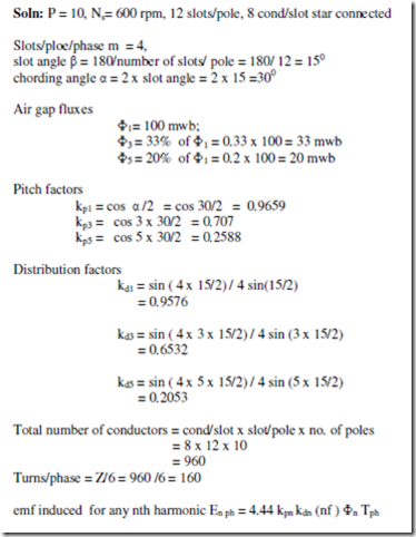
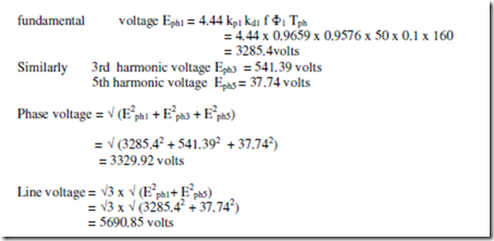
6. A 3 phase 10 pole 600 rpm star connected alternator has 12 slots/pole with 8 conductors per slot. The windings are short chorded by 2 slots. The flux per pole contains a fundamental of 100 mwb, the third harmonic having an amplitude of 33% and fifth harmonic of 20% of the fundamental. Determine the rms value of the phase and line voltages.
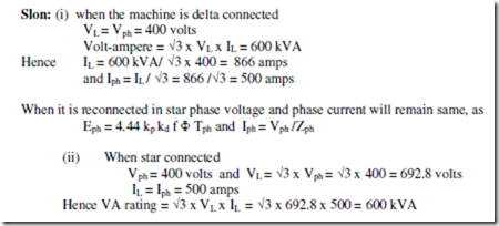
7. A three phase 600 kVA, 400 volts, delta connected alternator is reconnected in star. Calculate its new ratings in terms of voltage, current and volt-ampere.
Irrespective of the type of connection the power output of the alternator remains same. Only line voltage and line currents will change.
Related posts:
Incoming search terms:
- synchronous machines notes
- Calculate the rms value of the induced emf/phase of a 10-pole three-phase 50Hz alternator with 2 slots per pole per phase and 4 conductors per slot in twa layers The coil span is 150degress The flux per pole has fundamental component of 0 12Wb and a 20% t
- synchronous machine notes
- find the number of series turn required for 10 pole alternator
- a 3 phase synchronous machine star connected has the following datas: nunber of slot =192 condutors per slot=8 coil span=160° speed of the generator =375rpm flux per pole =50mwb calculate the phase and line voltage
- notes on synchronous machines
- synchornous mach
- Turns in a synchronous machine
- short note on synchronous machine
- notes about synchronous generator
- turns calculation for synchronous machine
- short notes on synchronous machines
- a 3 phase 2 pole 12 slots synchronous machine is operating at synchronous speed find the slot angle
- cross sectional area of condustor formula in nonsalientpole type conductor
- synchronous generator notes
- 4 pole star connected alternator running at 1500 r0m have 72 slot with
- A synchronous generator runs at 250 rpm at 50H There are 216 slots each containing 5 conductors arranged in full pitched winding for three-phase star-connection All the conductors of each phase are in series and the flux per pole at no load sinusoidally d
- alternator notes
- notes of synchronous machine
- synchronous motor notes
- Formula to find turns per phase in uniformly distributed alternatoI with double layer winding
- How to determine the number of poles in a synchronous machine when Number of conductors per slot is give
- in a synchronous machine if five is the flux per pole and f is frequency of induced e m f then
- A 3phase I M has slots/pole/phase=6 If the coil spsn=15slots determine winding factor
- slots 144 4 conductor per slots in 2 layer find total conductor
- slot angle in three phase synchronous motor
- motor winding calculation member of turn dobel laer 48 slots
- nots for synchronous machine
- reconnection of ac generator lead
- Rotor number of turn per core formula
- Deduce the expression showing the relationship between speed frequency and number of poles of a synchronous machine?
- alternater turn calculations formula
- 4 pole star connected alternator running at 1500 rpm have 72 slots with 10 conductor per slot the number of turns per phase and slot angle is
- why the rotor in turbo alternator are slotted two third of its periphery
- ac synchronous machine notes
- 4 pole star connected alternator running 1500 rpm having 72 slots with 10 conductors per slots the numbe of turns per phase and slot angle is
- salient pole rotor
- How to calculate number of turns per slot
- note on synchronous
- stator as rotor generator 500 kva
- how to calculate the coil of a alternator
- in a synchronous machine if is the flux per pole and F is the frequency of induced e m f then
- write brief note on voltag of a synchronous machine
- why the rotor in turbo alternator are slotted two third of its peripherry
- a 12 pole 3phase start connected alternator has 72slots the flux per pole is 0 0988wb calculate the terminal emf if the coil span is reduced to 2/3 of the pole pitch
- why 1 3rd prehery of rotor is unslotted in turboalternators
- why does the rotor of turboalternator are slotted for only two third of its periphery
- synchronous generater slots problems
- 48 Slots rewinding with data drowing
- 4 pole star connected alternator running at 1500 rpm have 72 slots with 10 conductors per slot the number of turns per phase and slot angle is
