HEADPHONES AND HEARING AIDS
Headphones offer the possibility of the ultimate private listening experience. Their small transducers can reproduce extremely low- frequency tones when connected almost directly to the ear, and their small size contributes to good high-frequency response. The privacy (therefore, low acoustic leakage), extreme bandwidth, and dynamic range possible at the ear make the headphone a vital professional tool and a relatively low cost, super-fidelity personal listening system.
HEADPHONES AND HEADSETS
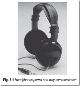
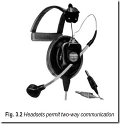
A headphone, Fig. 3.1, is defined as a listening device consisting of either one or two earphone receivers and a headband to hold them in place. A headset, Fig. 3.2, is essentially the same thing with a microphone attached to it. Headphones permit one-way communication while headsets permit two-way communication.
Particularly since the introduction of stereo, the use of headphones has become an important part of the high fidelity (hi-fi) scene, in some cases by choice and in others by necessity.
In the early days of wireless, headphones—often described as earphones—provided the most practical way of listening to the then available signals. From 1923 onwards, with the emergence of public broadcasting and the availability of more powerful receivers, loudspeakers rapidly gained favour especially for family listening. Headphones, however, were still widely used with professional and communication equipment until well after World War II.
TYPES OF HEADPHONES
Headphones are available in a vast assortment of shapes, sizes and types. Advertisements emphasize distinctive features even further, to the point where it is understandable that consumers get a little confused about the importance of features and forms.
In headphones, as in almost anything else, most of the differences exist merely as evidence of the manufacturer’s struggle to be distinctive, to market unique products.
One can identify three basic classes of headphones: (1) supra-aural (2) circum-aural, and (3) intra- aural.
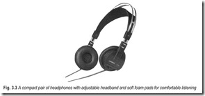
(1) Supra-aural (Fig. 3.3): Those that sit on the ears, usually pressing the external ear to the side of the head. Old versions of supra-aural headphones presented an uncomfortably hard bakelite or hard rubber surface to the ear. Nowadays soft cushions are the rule, some are foam or liquid filled and attempt an airtight seal to the irregularly shaped external ear. Others are fitted with large pads of acoustically transparent plastic foam and are designed in such a way that an airtight seal is not necessary.
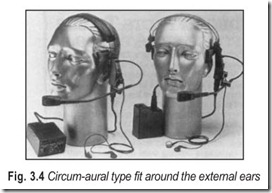
(1) Circum-aural (Fig. 3.4): Those with cushions that fit around the external ear, pressing directly against the head itself. In the best examples of circum-aural headphones the external ear is not deformed through contact with the unit.
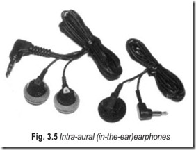
(2) Intra-aural (Fig. 3.5): These are in-the-ear or insert earphones of the type found in some aircraft, almost all hearing-aids and that are supplied for private listening to portable radios, tape recorders and TV’s.
These classes describe headphones by their construction and how they are worn, but they tell us little about factors important to stereo listening.
One important distinction among headphones can be made on the basis of whether they exclude external noise and prevent leakage of music to the outside world. The former is important for satisfactory listening in a noisy environment; the latter might be important in hospitals, libraries, or perhaps at home, where even the low level leakage of music can be a distraction to someone else.
In order for a headphone to have effective acoustic isolation it must provide:
(a) an airtight seal with the external ear (supra-aural) or the head (circum-aural) and (b) a totally enclosed cup over the ear, made of a rigid and relatively dense material.
These requirements eliminate headphones with electrostatic or electromagnetic membrane drivers (open backs) and porous cushion types (no airtight seal). Insert (intra-aural) earphones that fit the ear canal singly can be very effective at acoustic isolation.
MOVING-IRON HEADPHONES
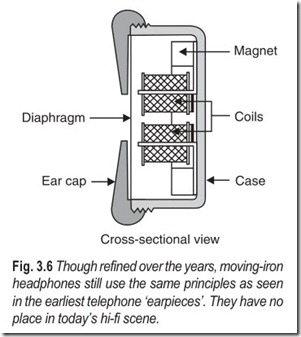
The so-called magnetic type (moving iron) headphones use the same basic principle as was originally adopted for telephone earpieces or receivers. As shown in Fig. 3.6 a thin flexible soft iron diaphragm is supported by the casing just clear of the tips of two soft iron pole-pieces which are attached, in turn, to a small permanent magnet. Magnetic attraction causes the diaphragm to be distended slightly towards the pole tips, while still leaving a clearance of something less than a half-millimeter.
The incoming audio current passes through coils wound around the pole-pieces. In the presence of an audio signal the varying magnetic field created by the current interacts with that from the permanent magnet, varying the pull on the diaphragm and causing it to vibrate, thereby generating corresponding sound waves.
Because of the inherent mass and stiffness of the metal diaphragm, headphones of this type suffer similar limitations to the old horn-type magnetic loudspeakers; a natural resonance at a few hundred hertz, resulting in the so-called ‘metallic quality’. They also exhibit quite high harmonic distortion due to the fact that the diaphragm drive is one-sided or unbalanced.
CRYSTAL HEADPHONES
In the 1950s and 1960s an assortment of crystal earphones appeared on the market, being essentially miniaturised counterparts of the crystal (or piezoelectric) loudspeakers.
Involving few metallic components, they could be made very small and light, as well as lending themselves to mass production. Many, infact, were designed to plug directly into the ear canal, being intended for use with portable radio sets and tape players. A few special quality models have been released over the years for monitoring situations but in general, crystal headphones have slotted into a utility role rather than as a medium for hi-fi listening.
As with crystal loudspeakers, their impedance is predominantly capacitive, measuring many thousands of ohms at low and mid frequencies. This may not present a problem where sufficient signal drive voltage is available, but with ordinary low-impedance drive circuits, their effective sensitivity is likely to be poor compared with magnetic units.
DYNAMIC HEADPHONES
The widespread adoption of dynamic or moving-coil loudspeakers in the 1930s raised the question as to whether it would be possible to use the same principle for headphones. If the drive units could be made small enough and light enough, they would presumably offer equivalent frequency response and much reduced distortion.
Moving-coil earphones designed in 1936 and released in 1937 were discontinued in 1939 as too cumbersome and too expensive to justify continued production. But by 1967 twenty seven firms had entered the market and one-time descriptions like heavy, cumbersome, and metallic had also given way to light- weight, comfortable, and high quality, with headphone listening rapidly becoming an accepted part of the hi-fi stereo scene.
Because it was the most accessible approach, many of the dynamic headphones introduced to the post- war hi-fi market comprised, essentially, of two miniature (50 –70 mm) loudspeakers housed in shells rather like the two halves of an electromagnetic unit egg.
Typically, the oval shells of a pair of middle-aged Japanese-made Golding dynamic headphones measure about 10 cm tall, 9 cm wide, and 5 cm deep. They are fronted by a gold anodized grille with two matching pressure relief ports at the rear. The shells are cushioned with a removable pad, while the headband is adjusted and padded. While bulky and by no means light, the treatment gives them a soft and friendly feel.
One can reasonably expect that equivalent models from reputable sources would incorporate drivers with magnets, cones and voice coils selected for the role and with the shells physically styled and acoustically treated for the best available end result. With outside noise largely excluded, and operating so close to the ears, the drivers can be expected to produce an ample sound pressure level (SPL) with only milliwatts of input thereby minimising cone break-up and non-linear distortion.
Being damped by both the front and rear air loading, cone resonance effects are held in check, flattening frequency response. Subjectively, high frequencies are projected directly into the ear canal while the captive air inside the cushion surround also conveys low frequency pressure waves efficiently to the eardrums. Most such headphones are capable of sound quality far better than is available from traditional magnetic earphones.
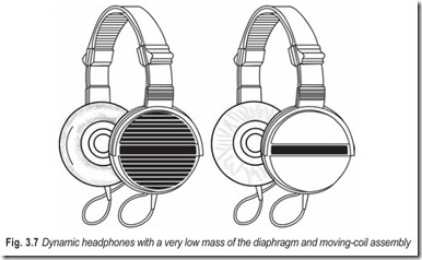
While such headphones are still in use, many people find them too cumbersome for prolonged listening and, in a warm environment, too hot around the ears. Now-a-days most stereo headphones are much smaller and lighter, using specially developed ultra-compact drivers. Some retain paper based cones; others retain a dome type diaphragm similar in configuration to the squawker and tweeter loudspeakers. A few up market models include their own diminutive tweeter. Dynamic headphones are shown in Fig. 3.7.
ELECTROSTATIC PHONES
Another type of headphone needs a special mention at this juncture—those using the capacitive or electrostatic principle.
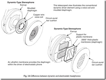
A very thin, partially conductive plastic membrane, is supported just clear of a metallic surface being, at the sametime, attracted towards it by an electrostatic charge. An audio signal voltage, applied to either element, adds to or subtracts from the charge, causing the membrane to vibrate and produce sound waves.
This obviously parallels the earlier explanation of a magnetic earphone (Fig. 3.8) but with the vital difference that a plastic membrane can have much less mass and stiffness than a metal diaphragm, thereby minimising problems with system resonance and uneven response over the working range. It also lends itself to a balanced configuration minimising harmonic distortion.
In early model electrostatic headphones, as with their headphone counterparts, a high dc polarising voltage had to be fed to the phones along with a fairly high audio drive voltage. This meant, in practice, that electrostatic headphones could be simply plugged into a socket provided for dynamic headphones. An external adapter was required, containing a mains powered high voltage supply and a step-up transformer for the audio drive signal.
ELECTRET ELECTROSTATIC HEADPHONES
In the mid-1970s permanently polarised or electret elestrostatic headphones made their appearance, with Sennheiser Models 2000 and 2002. While the need for a mains powered h.t. supply had been eliminated, they still need an external black box containing twin step-up transformers, to permit operation from the amplifier voice coil output terminals.
In fact, Sennheiser made a virtue out of necessity by arranging for the adapter to feed two separate pairs of electrostatic headphones as well as providing loudspeaker/ headphone switching. The company also included protection circuitry to limit the sound pressure level from the phone to 117 dB, alongwith l.e.d. indicators to show when the circuitry was being activated.
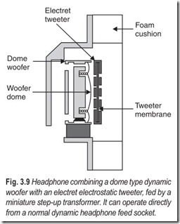
About the same time, AKG brought out its two-way 4K headphones which, despite their modest dimensions, were a two-way design combining a dynamic driver and electret tweeter crossing over at 4.5 kHz.
As indicated in Fig. 3.9, the woofer is deep inside the casing. Using a highly efficient rare earth/cobalt magnet and a moulded polycarbonate diaphragm, it can operate directly from a normal amplifier headphone socket. Its rated low end response extends to 16 Hz but, at the top end the body of the tweeter serves to block physically its residual output above the nominal crossover frequency.
The tweeter uses the electret principle, with a 12.5 micron chromium-sputtered foil optimised for the frequency range above 4.5 kHz. The higher drive voltage required is provided by a 1:5 step-up transformer, which can be made extremely small by virtue of the fact that it needs to handle only frequencies above 4.5 kHz, falling off steeply below that.
For the design, AKG claimed the best of both worlds—the ability to operate from a normal headphone drive circuit and the reputed sonic transparency of an electroacoustic transducer for the top end.
HEARING IMPAIRMENTS
There are millions of people in the world with hearing impairments. It is surprising that the special hearing needs of so large a group have been largely ignored for so long, especially when each of us faces the very real probability of joining that group through disease, trauma, or just by growing old.
The hearing impaired are not just the people who wear aids. In fact, only about 20% of the hearing impaired wear aids. Many people with hearing losses are able to function in close or face-to-face situations but are lost in noisy or reverberant settings. Even people who wear hearing aids have problems in reverberant rooms or where there is a high background noise level. Our standards for speech intelligibility are based upon listening tests with normal hearing subjects and are not directly applicable to the hearing impaired. Noise and reverberation degrade intelligibility far more rapidly for the hearing-impaired individuals—whether they are fitted with hearing aids or not. Often the very highly prized acoustical qualities of our theatres and concert halls operate against the needs of the hearing impaired. The acoustical design of classrooms and lecture halls are almost always inadequate for the needs of the hearing-impaired student.
In recent years whole new technologies have been developed or adapted to meet the special needs of the hearing impaired in public assembly spaces. Each of these new systems has one thing in common—they are wireless.
AUDIOMETRY
Audiometry is the general term applied to a number of tests used to measure hearing.
An audiometer is an essential instrument for conducting most audiometric tests. The audiometer is basically a device that generates pure tones of known level and frequency, and delivers these to the patient through either a headphone or a bone conduction vibrator.
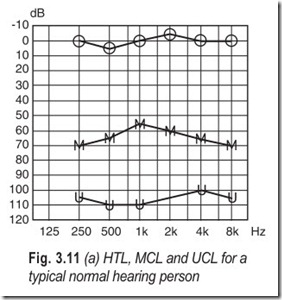
On an audiometer, the levels are given as Hearing Level, dB (HL). In this way, a normal hearing person will be able to hear tones at and above a 0 dB HL level.
Since these levels are average levels measured in a standard coupler, the actual sound levels at the patient’s eardrum can differ considerably. One might expect up to as much as 15 dB individual deviation from the average.
Instead of using headphones one can use insert earphones, where the transducer, by means of an earplug, is inserted into the ear canal. Insert earphones offer some advantages regarding reduction of possible masking effects from environmental noise during audiometry. Also in the case of non-symmetrical hearing loss, insert earphones are preferable, as their coupling to the opposite ear is minimal. Finally, insert earphones can be used in cases where the ear canal collapses when using conventional earphones.
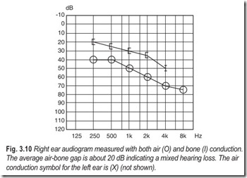
When recording the air conduction threshold the sound must pass through the ear canal and the middle ear to reach the hair cells in the inner ear. When the bone conduction threshold is recorded, a bone conductor is used. The signal then by-passes the ear canal and middle ear and is conducted directly through the bones of the cranium to the inner ear. Therefore, if the air conduction threshold is worse than the bone conduction threshold (an “air-bone gap”), the reason must be found in the ear canal or in the middle ear.
An audiogram contains information about the hearing loss at a number of frequencies. The total hearing loss, as measured with headphones at any frequency, is called the air conduction hearing threshold level. The sensory part of the hearing loss, as measured with a bone conductor, is called the bone conduction level, or bone conduction threshold. Note that not all audiometers have a bone conductor facility.
The audiogram is a graphic representation of the audiometric results. Fig. 3.10 shows an example of an audiogram.
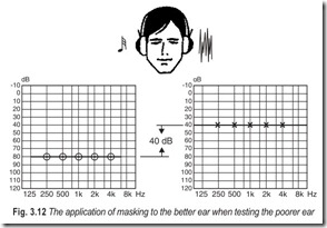
have different thresholds, the good ear should be tested first. If the hearing loss on the bad ear is 40 dB or more below the (bone conduction) level of the good ear, masking should be used to cancel out the effect of bone conducted sound.
A source of measurement error is background noise. This will cause the threshold to be worse, due to masking of the test ear. Therefore, audiometry is normally carried out in a sound treated test booth.
Bone Conduction
It is important to distinguish between conductive losses (in the outer ear or in the middle ear), sensorineural losses (in the inner ear, in the nerves or in the auditory pathway) and mixed losses (a combination of a conductive and a sensorineural loss).
For this purpose, the bone conduction threshold is often included in the audiogram. For measuring the bone conduction threshold, a small vibrator is usually placed on the scull (mastoid) just behind the ear, instead of the headphones. This vibrator is called a bone conductor. The bone conductor should not touch the pinna during testing, as vibrations could be sensed from its casing, causing a false result.
The difference between the bone conduction and air conduction thresholds is called the air-bone gap. The extent of the air-bone gap is a measure of a possible conductive component of the hearing loss. In a sensorineural loss, no air-bone gap is present. Small differences, up to 10 dB, can be considered insignificant. Such differences can be the result of individual variations in the coupling between the vibrator and the scull. The average air-bone gap (a measure frequently used in the fitting process) can be calculated as the average of the air conduction and bone conduction differences over the frequency range evaluated. An air-bone gap of 15 dB or more, indicates a true conductive component.
Distortion in the bone conductor renders the results at low frequencies less reliable than the air conduction measurements. With a flat hearing threshold curve, only the high frequencies are valid. With steeply sloping curves, a larger air-bone gap is necessary to make sure a true conductive loss is present.
The sound from the bone conductor can often be heard equally well in both ears. The bone conduction threshold is therefore a measure of the best ear at that frequency. If the bone conduction threshold for one ear only is to be measured, the opposite ear must be masked with noise.
Un-Comfortable Level (UCL)
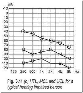
The Un-Comfortable Level, UCL, refers to the level above which the patient will not accept listening. Un- Comfortable Level is also referred to as Threshold of Discomfort (TD) or Uncomfortable Loudness Level (ULL).
This measurement is relevant to both diagnostic and hearing aid fitting purposes. Together with the hearing threshold, the UCL gives an indication of the total hearing range, the dynamic range.
Most Comfortable Level (MCL)
The level at which a person prefers to listen to a particular sound for a long period of time is called the Most Comfortable Level (MCL). MCL can be recorded for pure tones and for complex sounds such as speech and noise. When an MCL is recorded on several occasions, the variation observed may amount to 10 – 15 dB, or even more. Often, an MCL is estimated without measurement to be midways between the hearing threshold and the uncomfortable loudness level. MCLs are commonly used in hearing aid fitting to estimate the most suitable gain requirement.
Masking
When two ears differ substantially in hearing sensitivity, problems can arise when testing the poorer ear. The problem is that intense sounds, which are necessary to test the worse ear, may be detected by the better ear. Sound waves can give a sensation of hearing through two different pathways. The most efficient of these pathways is through the ear canal, the middle ear, and on to the cochlea. Also, sound vibrations can travel through the skull to the cochlea. If one ear is better than the other, it risks picking up vibrations caused by the loud sounds used to test the poorer ear. This may cause the patient to respond when the sound is still too weak to be heard in the worse ear. Masking is used to eliminate this problem.
Masking is the presentation of a noise signal to the better ear sufficiently loud to prevent the test stimulus from being heard in that ear. As a rule of thumb, masking is applied in air conduction measurements if the difference between the two ears is 40 dB or more. With a conductive hearing loss there are special problems. Masking should then be applied to the better ear when its bone conduction threshold differs more than 40 dB from the worse ear’s air conduction threshold.
When the poorer ear is tested, a masking noise signal from the audiometer is presented to the better ear. By varying the level of the masking noise, it is possible to register whether the tone is heard in the test ear (the poorer ear), or whether the sound is erroneously detected by the opposite, better ear.
Speech Audiometry
In speech audiometry a number of test words or sentences are presented to the patient. The speech signal may be presented through earphones or, when e.g. a hearing aid is to be evaluated, through loudspeakers. Presentation through loudspeakers is called sound field testing.
The Speech Reception Threshold (SRT ) is recorded by varying the level of speech until a certain proportion of the test words is correctly identified. SRT is typically the level at which the patient can understand 50% of the words presented. Normally, material consisting of numbers or two-syllable words is used for assessing SRT.
Very often, speech testing is carried out at a higher presentation level, often at the most comfortable level. The percentage of correctly identified test words is called the “speech recognition score.” Often, the older term “speech discrimination score” is used instead. Also the term “speech recognition loss” may be used, meaning the difference between a perfect score of 100% correct and the score actually obtained.
Speech audiometry can be used to compare the effect of different hearing aids or different settings of the same hearing aid. Caution should be taken in interpreting such scores, since they may differ substantially from test to test just by chance. A number of factors other than those related to hearing may influence the scores. Such as training, education and even dialectal background of the patient.
Impedance Audiometry
Impedance audiometry offers a convenient means of registering the status of the middle ear. A low frequency tone is presented in the closed ear canal. The level of the tone will be higher when the eardrum is rigid (immobile), compared to when it is compliant.
By this means it is possible to measure the static pressure in the middle ear, the integrity of the middle ear ossicles, whether the middle ear cavity is filled with fluid or air, and whether the middle ear muscles are activating or not (the acoustic reflex).
HEARING AIDS
The basic function of a hearing aid is to amplify sound in such a way that it is made audible to the hearing aid user. Although many types of hearing aids are available, they all share a number of common features. We will look in some detail at the various hearing aid types, their components and electroacoustic characteristics.
Full Concha Model
The full concha model will occupy most of the concha of the outer ear. It can provide more amplification and output than the canal model. A variation of this model is called a “semi” or “half” concha, in which the helix part, or most of it, is removed.
Canal Models
Canal aids, especially in their CIC format (Completely In the Canal) are the smallest type of hearing aid available. Because of its small size, only miniature batteries and receivers are used, causing limitations in amplification, output and battery life. The receiver and microphone are placed so close to one another that the risk of feedback is higher than in other models. Therefore, canal aids are used mainly for mild-to- moderate hearing losses.
Body Worn Aids
In most instances, body worn aids are used for those having severe to profound hearing losses. In some cases, they are used when the user has difficulty in handling other types of hearing aids. Such may be the case for the very young or very old hearing impaired person.
A body worn aid can provide more amplification than other hearing aid types because the receiver is separated from the hearing aid by a cord. This reduces the risk of feedback, permitting more power to be utilised. The receiver is snapped onto the earmould. The body worn aid is worn in a pocket or can be hidden by clothing. Very young children often use a microphone cover to prevent food from damaging the microphone.
Hearing Glasses
In hearing glasses the amplifier, microphone and receiver are built into the side arms. This was for many years a popular way of camouflaging a hearing aid and some users found hearing glasses easier to manipulate than BTEs. However, the practical drawbacks of combining visual and hearing rehabilitation into one device have become so evident that hearing glasses are now slowly disappearing from the market.
A variation of hearing glasses is the use of adapters which connect a BTE hearing aid to the side arms of spectacles.
CROS/BiCROS
Hearing glasses are often used in a CROS application (Contralateral Routing Of Signals), where the spectacle frame is used to conceal the wires. CROS applications are sometimes used to fit asymmetrical losses. The microphone (in an empty hearing aid case) is mounted on the side having the more severe hearing loss. The amplifier and the receiver are mounted on the other side. The signal from the microphone is led to the amplifier, either via a cord or using wireless transmission. In most cases, it is possible to use an open mould.
A simple CROS application is used when the user has a severe hearing loss, or no hearing at all, in one ear and close to normal hearing in the other. A slightly more complicated application is the BiCROS fitting, which may be used when the user has a severe or profound hearing loss in one ear and a moderate hearing loss in the other. In this case, two microphones and one amplifier are used, providing the user with an amplified signal from both sides.
Hearing Aid Models
Hearing aids are divided into four main groups.
1. Behind The Ear (BTE)
2. In The Ear (ITE)
3. Body worn aids
4. Hearing glasses
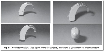
The BTE hearing aid is a widely used model. It is placed behind the ear, and the sound is conducted to the ear canal through a plastic tube and an earmould. BTEs can be used for the majority of hearing losses. They are the typical choice for severe losses due to their gain and output capabilities and the possibility of combining them with educational equipment via audio input.
The ITE hearing aid is placed directly in the cavity of the outer ear. All parts of the hearing aid are built into the earmould. One advantage of the ITE hearing aid is that the “natural” effect of the outer ear (pinna) is maintained, making it easier to determine the direction of the sound source and take advantage of the natural high frequency amplification of the pinna.
ITEs can be modular or custom made. In the modular type, the hearing aid is a complete functioning unit so small that it can be placed entirely within or onto an earmould. This makes it easy to replace and repair the hearing aid. Custom made models can be made slightly smaller in size, but at the expense of ease of replacement and repair. Both types are available in two basic models: full concha and canal.
INSIDE A HEARING AID
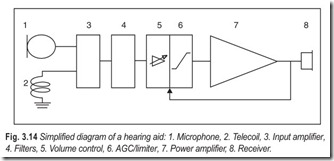
The main components of a hearing aid are :
1. An input transducer, (a) microphone or (b) telecoil
2. An amplifier with volume control, filters, automatic gain control (AGC) and max. output regulation.
3. A receiver (loudspeaker)
4. A battery
The Microphone
The microphone converts sound waves into electrical signals. The electret microphone is the most commonly used type. It is a special type of condenser microphone with a built-in low-noise preamplifier. The electret microphone has a smooth frequency response and a low sensitivity to mechanical vibrations. This reduces the risk of acoustic feedback.
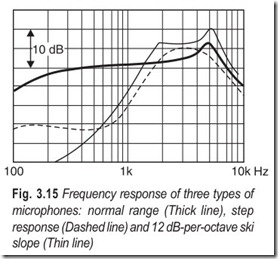
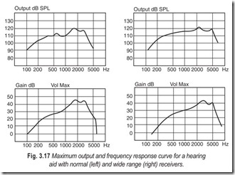
Hearing aid microphones exist in a number of versions having different frequency responses and sensitivities. Some hearing aid types are available with optional microphones. The most commonly used microphones are; normal range, wide range, 6 or 12 dB per octave ski slope, step response and damped peak microphones.
As an alternative to shaping the frequency response with special microphones, electric filtering techniques have become more common. These techniques may be preferable with regard to reducing internal noise from the microphone.
Microphones can be omnidirectional or directional. Most microphones used in hearing aids are omnidirectional, meaning that sound is received from all directions with almost equal sensitivity.
To improve speech discrimination in noise, a directional microphone can be used in BTE hearing aids with the effect that signals coming from behind are being suppressed, thus improving the user’s ability to attend to the frontal sound source. In reverberant situations, the positive effect of directional microphones is diminished.
Note that directional microphones normally have reduced sensitivity at low frequencies compared to normal microphones.
The Telecoil
A telecoil transforms variations in a magnetic field into electrical signals which can substitute the signal from the microphone. The telecoil is used in connection with a teleloop system, which are installed in places such as theatres, churches and schools for the hearing impaired.
A loop system consists of a loop amplifier and a teleloop. A well functioning system produces a magnetic field representing the sounds to be heard. Hearing aids equipped with a telecoil can convert this magnetic field into sound when the telecoil is activated (M-T switch in position T). In this way, background noise may be reduced. A small telemagnetic system can be used in private homes for listening to TV. A telephone adapter can be used for telephone communication.
Audio Input
A good sound quality can also be obtained by using an electrical input connection directly on the hearing aid, known as an audio input system. This is often used in educational situations, and frequently in connection with radio (FM) or infrared transmission.
The Amplifier
Signals from the microphone or the telecoil are fed to the amplifier. This weak low-energy signal is transformed into a powerful electrical signal which drives the hearing aid receiver. There are different types of amplifiers. The class A amplifier uses the same high amount of current whether there is a signal at the microphone or not. It has now been almost completely replaced by amplifiers with lower current consumption.
The linear push-pull amplifier (Class B), and modern variations of it, are far more economical and have very little distortion. Power consumption is low whenever the signal is weak, and higher when a stronger signal is present at the microphone.
Switching amplifiers utilise pulse modulation to increase the useful effect of the amplifier. The amplifier may be partly integrated into the receiver. Switching amplifiers are characterised by low distortion and high efficiency. One type of switching amplifier is called Class D.
Amplifiers can be made either with discrete components mounted onto a printed circuit board, as thin- film or thick-film circuit blocks, as integrated circuits (IC), or as a combination of these.
The Discrete Amplifier
The discrete amplifier has individually mounted components and it takes up more physical space than other types of amplifiers. It is, therefore, used primarily in large hearing aids such as body worn aids and large BTEs.
Thin Film Amplifier
The thin film amplifier is built onto a thin ceramic or glass plate covered with a resistive material. Individual resistors are made by an etching process and the connections are achieved by adding gold to the surface. By using thin film techniques, it is possible to make very precise resistors. Transistors, integrated circuits and capacitors are mounted onto gold connectors. Connections are made with thin gold wires, using a special bonding process.
Thin film circuits normally have only one layer of connections on each side. The connections from one side to the other are difficult to make and are relatively large and thereby impractical. Consequently, thin film circuits are often made single sided.
Thick Film Amplifier
The thick film amplifier consists of a thin ceramic plate, on which resistors and connectors are “printed” onto the surface by using a special silk screen technique. These resistors and connectors are larger than those for thin film, and the resistors have to be adjusted if they are to be precise. It is possible to make many layers and to make connections between the layers and the two sides. The thick film technique is the most commonly used process today. It is often used in connection with integrated circuits. Transistors, integrated circuits and capacitors are mounted onto the surface, often on both sides of the ceramic plate.
Integrated Circuits (IC)
The IC component, the size of which is often only a few square millimeters, may contain several thousand transistors and resistors. The IC has made it possible to make hearing aids smaller and more sophisticated than before. Hearing aids often use an IC which is “custom” made for a specific hearing aid model.
In the process of designing an IC, Computer Aided Design tools (CAD) are used. Generally, the design phase has become more complex, while the production phase has been simplified.
The Receiver (Loudspeaker)
The receiver converts the amplified electrical signal into sound waves. There are different receiver types, both in size and performance. Generally, size determines the sensitivity and the maximum output of the receiver. By using an acoustic filter, the frequency response and the frequency range may be improved.
Batteries
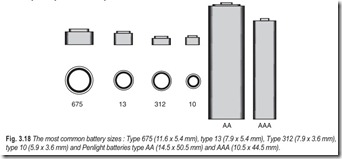
Batteries are available in different sizes and types and the most commonly used are zinc air batteries. Zinc air batteries have high energy density, they are affordable, and used batteries have little impact on the environment.
Battery capacity is measured in milli-ampere hours (mAh). For instance, if a battery having a 100 mAh capacity is used in a hearing aid with a battery drain of 1 mA, it will last approximately 100 hours. Battery drain for modern amplifiers depends on the output produced by the hearing aid. Therefore, battery drain cannot always be specified exactly.
For hearing aids with extremely high power consumption, or for powerful aids in heavy duty use, mercury or silver oxide batteries are still used. However, modern zinc air batteries are very competitive, coming close to the performance of mercury and silver oxide batteries.
Alkaline batteries are used for body worn instruments and hearing aid remote controls.
USER OPERATED CONTROLS
The Volume Control (VC)
Most hearing aids have a volume-control, which enables the user to adjust the amplification of the hearing aid according to the different listening environments. Some hearing aids have no VC accessible to the user. Instead they are equipped with some sort of automatic gain control and the gain is preset by the manufacturer or the hearing healthcare professional.
The On/Off switch
The hearing aid is turned on or off by using the on/off switch. This can either be a tiny switch, mounted on the hearing aid case, or it can be integrated into the battery compartment for ease of operation.
The M-T switch
Many hearing aid models are provided with a switch, enabling the user to choose between receiving the signal, either from the microphone, or a telecoil loop system. This is called the M-T switch. The hearing aid receives the signal from the telemagnetic loop system whenever the M-T switch is in the T position. The telecoil system is often used in theatres, cinemas and churches. With a well adjusted telemagnetic system, the use of the telecoil, instead of the normal microphone input, may improve sound quality significantly in situations where background noise is present and there is a relatively large distance to the sound source.
When the hearing aid is in T mode, the microphone is disabled. In some situations, it may be advantageous to use T and M simultaneously, e.g. when listening to the TV via the telecoil, while still wanting to hear speech, the door bell or other important environmental sound. For this purpose, some hearing aids have an MT mode which activates both the microphone and the telecoil simultaneously.
The N/H switch
Some hearing aids have a normal response/high tone switch (N-H switch), often instead of the M-T switch. When placed in the H position, the N-H switch will change the sound from normal response to high tone emphasis by attenuating the low frequencies. This improves speech discrimination in noisy environments, e.g. traffic, subways, in a car.
Program selection switch
Some multi-program hearing aids have a program selection switch on the hearing aid.
Remote control
Many hearing aid users prefer to control their hearing aids in a more sophisticated manner. They want to select from a larger number of features, depending on the listening situation. Since the hearing aid user often wants a rather small and cosmetically acceptable hearing aid, such controls cannot be implemented in traditional ways with switches and trimmers.
Instead, it is possible to provide hearing aid models with several user selected programs. Such a program contains a combination of acoustic parameter settings, matched to provide optimum listening for a particular user in a certain listening situation. By using a remote control, the user can select from a number of preset programs. The transmission pathway from the remote control to the hearing aid is either based on infrared light, ultrasonic sound, or radio waves. By the simple press of a key on the remote control unit, the hearing aid user has immediate access to the best acoustic response for a given listening environment.
DISPENSER OPERATED CONTROLS
Most hearing aid models have facilities to adjust the hearing aid for the individual hearing loss. These facilities, which vary from switches and trimmers, to computer operated digital memories, are used to adjust
e.g. amplification of low or high tones, maximum output, preset gain and compression (automatic gain control (AGC)).
Preset Gain Control
The hearing aid often has a preset gain control permitting a reduction of the maximum gain by up to 20 dB. The preset gain is adjusted to a position giving the user the most suitable operating range for the volume control. The preset gain control is also used to reduce maximum gain in order to avoid feedback (whistling). This function can be useful for children or for those having difficulties adjusting the volume control.
Preset gain control can also be used to create binaural loudness balance, as well as to equalise the balance for different programs in a multi-program hearing aid.
FILTERS
Low-Cut Filter
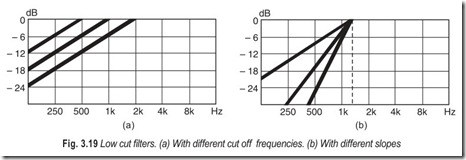
The low-cut or bass-cut filter is used to reduce amplification of low frequencies. This filter is used if the hearing impaired person has normal or near normal hearing in the low frequencies, or experiences trouble hearing in noisy environments.
There are various degrees of filter slopes, ranging from a slope of 6 dB per octave in a traditional, first order passive filter, to 12, 18 or 24 dB per octave in an active filter (which contains an amplifier). Special tone filters may have a variable slope.
The number of filtering components (such as capacitors) determines the order of the filter. A first order filter can be designed using only one capacitor, while four are needed in a 4th order filter.
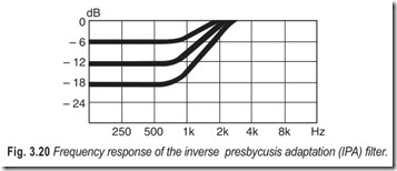
The majority of hearing impaired people suffer from hearing loss due to the aging process (presbycusis). They hear low frequencies without significant problems, but have impaired hearing in the high frequencies. Therefore, a special filter, the Inverse Presbycusis Adaptation (IPA) filter, has been designed to compensate for this type of loss.
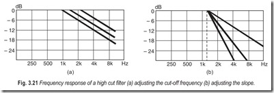
High-Cut Filter
A high-cut filter is used to reduce amplification of high frequencies, normally above 1000 Hz. This reduction is also useful for those with a severe hearing loss, to reduce the risk of acoustic feedback. The filter may, furthermore, be used for first time hearing aid users, in order to attenuate the high frequencies. This is often preferred in the early stages of hearing aid use. After a while, the user becomes accustomed to the hearing aids. It is then possible to change the high-cut filter response to increase amplification of the high frequencies.
The high-cut filter can also be a first order or higher order filter, as described for the low-cut filter.
OUTPUT CONTROLS AND AGC
The amplification of a hearing aid should be provided in a way which makes the amplified sound audible without being uncomfortably loud. If the sound is too loud at a certain frequency, the user may turn down the volume control to a point where the gain at other frequencies is insufficient.
The highest sound level, a certain hearing aid can produce, is specified as the maximum output level of that aid. If this level is too loud for the user, it must be reduced. The output control and the compression control are used to accomplish this task.
The Output Control
The best way to reduce the output of a hearing aid will depend very much on the properties of its output control and AGC circuit. Normally, the output control; when used alone introduces some distortion. Therefore, it is normally used in connection with AGC in order to minimise distortion.
The Compression Control
The original idea with a compression circuit was to compensate for recruitment by compressing the large amplitude variation of daily sounds into the more narrow dynamic range of an impaired ear. This type of compression, however, may not function well in background noise. Currently, another type of compression, a limiting compressor, is the most frequently used type of compression. A limiting compressor reduces the output in a way similar to that of the output control, but without introducing distortion. It is used to prevent loud sounds from reaching uncomfortable levels. By using compression, the hearing aid user will not be forced to reduce the gain (and thereby make soft speech components inaudible) in order to avoid a few intense sound impulses from becoming uncomfortably loud.
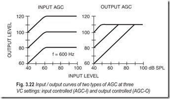
A compression circuit may be placed either before or after the volume control. This placement influences the way it functions. If it is placed before the VC, it is denoted input AGC (AGC-I). When placed after the VC, it is called output AGC (AGC-O). Input AGC is activated at a certain level of the input signal, independently of the VC setting. Output controlled AGC secures that the output never exceeds a preset level independent of the VC setting.
A dynamic characteristic is superimposed.
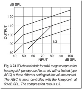
A different type of AGC is designed to be active during normal speech input. It reproduces the overall level of the input signal as a reduced variation of the output signal. The slope of the input-output characteristic gives the compression ratio (see Fig. 3.23). The input/output (I/O) curve is a steady- state characteristic, valid only for slow level changes.
When fast level variations occur, as in normal speech, the gain will only vary minimally, due to the slow release of the AGC circuit. Thus, the dynamic characteristic will be a curve characterised by a constant gain. In the diagram this appears with a 1:1 slope.
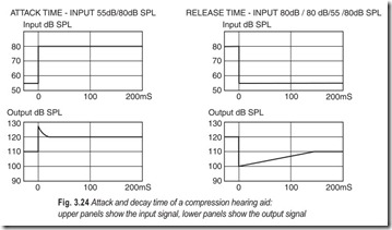
A sudden loud sound will activate the compression circuit. It takes a certain amount of time before the compression is fully activated. This duration is called the attack time. When the loud sound stops, the compression will gradually become inactive. The duration of this process is called the release (or decay) time.
OTHER TYPES OF AGC
A large number of AGC types have been developed during the past decades. They all have the common purpose of automatically adjusting the gain and/or the frequency response of the hearing aid in accordance with the input signal and the user’s dynamic range.
Multi-Channel AGC
In multi-channel AGC, the input sound is divided into two or more frequency channels, each of which has its own AGC circuit. Multi-channel AGC has the positive feature that a loud sound in one frequency band will not affect amplification in a different frequency band. On the other hand, there is a tendency for a spectral smearing diminishing spectral contrasts. Such smearing may have a negative effect on speech intelligibility, and hence hearing aid acceptance.
Automatic Signal Processing, ASP
ASP essentially denotes a way of automatically adjusting the low frequency cut-off according to the content of intense, low frequency components of the input sound. If dominating low frequency components are present in the input signal, as e.g. in a car or in heavy traffic, the low frequency gain is automatically reduced to prevent spread of masking.
Such a bass reduction may also prevent the hearing aid from being overloaded and sounding distorted.
Loudness Compensating AGC
A number of AGC circuits, including the so-called K-amp, aim at compensating for abnormal growth of loudness, which is seen in many hearing impaired persons. The net effect is that the need for adjusting the volume control becomes less.
Adjustment of hearing aids with loudness compensating AGC is often quite specific for each type of instrument. In general, the adjustment is performed on the basis of the audiogram, as well as measurements of loudness perception. Usually the fitting is carried out using a computer or a dedicated programming device.
EXERCISES
Descriptive Questions
1. Differentiate between headphones and headsets.
2. What are the different types of headphones based on their construction?
3. Explain the working of a dynamic headphone.
4. Discuss the working of electrostatic headphones. How do they differ from other headphones?
5. What are the peculiarities of electret–electrostatic headphones?
6. Discuss the limitations of various types of headphones?
7. What are the requirements of a hearing aid?
8. Explain the different types of hearing aids.
9. What are the controls associated with hearing aids?
Multiple Choice Questions
1. Moving iron headphones work on the principle of
(a) magnetic attraction (b) magnetic repulsion
(c) both (a) and (b)
2. Moving iron headphones suffer from
(a) natural resonance (b) high harmonic distortion
(c) non-linear distortion (d) none of these
3. The drivers of dynamic headphones can be expected to produce
(a) ample sound pressure level (b) insufficient sound pressure level
4. Electrostatic headphones
(a) suffer from system resonance (b) are free from system resonance
5. Which one of the following suffers from high harmonic distortion
(a) moving iron headphones (b) moving coil headphones
(c) electrostatic headphones (d) crystal headphones
6. Which one of the following headphones needs polarizing voltage
(a) moving coil (b) electrostatic
(c) moving iron (d) crystal
Fill in the Blanks
1. permit one-way communication.
2. permit two-way communication.
3. Interaction between the two fields in moving iron headphones varies the on the diaphragm causing it to .
4. Plastic membranes can have much less and than metal diaphragms thereby minimising problems with .
5. The impedance of crystal headphones is predominantly .
6. Electrostatic headphone lends itself to a configuration minimising .
7. Electret electrostatic headphones are permanently .
8. LED indicators in headphones indicate that the circuit is .
ANSWERS
Multiple Choice Questions
1. (a) 2. (a) 3. (a) 4. (b) 5. (a) 6. (a)
Fill in the Blanks |
||
|
1. Headphones 4. mass, stiffness, system resonance |
2. Headsets 5. capacitive |
3. pull, vibrate |
6. balanced configuration, harmonic distortion 7. polarised
8. activated
