By m/Nr winding model, we mean the induction motor with m stator windings and Nr actual (rotor loop) windings. [29]
In the general case, the stator windings may exhibit faults such as local short-circuits, or some open coils, when the self and mutual inductances of stator windings have special expressions that may be defined using the winding function method. [30,31, 32]
While such a complex methodology may be justifiable in large machine preventive fault diagnostics, for a symmetrical stator the definition of inductances is simpler.
The rotor cage is modeled through all its Nr loops (bars). One more equation for the end ring is added. So the machine model is characterized by (m + Nr + 1 + 1) equations (the last one is the motion equation). Rotor bar and end ring faults so common in IMs may thus be modeled through the m/Nr actual winding model.
The trouble is that it is not easy to measure all inductances and resistances entering the model. In fact, relying on analysis (or field) computation is the preferred choice.
The stator phase equations (in stator coordinates) are
Va = R is a + ddtΨa
Vb = R is b + dΨb (13.147)
dt
Vc = R is c + ddtΨc
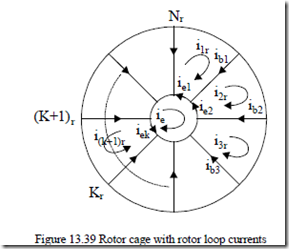
The rotor cage structure and unknowns are shown in Figure 13.39.
|
Figure 13.39 Rotor cage with rotor loop currents The Krth rotor loop equation (in rotor coordinates) is |
|
|
0 = 2Rb + RNer ikr + dΨdtkr −R ib ( (k 1 r− ) +i(k 1 r+ ) ) Also, for one of the end rings, |
(13.148) |
|
0 = R ie e + Le die −∑Nr Re ikr + Le dikr |
(13.149) |
dt 1 Nr dt
As expected, for a healthy cage, the end ring loop cage current ie = 0. The relationships between the bar loop and end ring currents ib, ie are given by Kirchoff’s law,
ibk = ikr −i(k 1 r+ ) ; iek = ikr −ie (13.150)
This explains why only Nr + 1 independent rotor current variables remain. The self and mutual stator phase inductances are given through their standard expressions (see Chapter 5).
Laa = Lbb = Lcc = Lls + Lms
Lab = Lbc = Lca = − 12 Lms (13.151)
Lms = 4πµ2K p g 10 (cWK11 (w1+)2KτsL)
The saturation coefficient Ks is considered constant. Lls – leakage inductance, τ – pole pitch, L – stack length, p1 – pole pairs, g – airgap, W1 – turns/phase, Kw1 – winding factor. The self inductance of the rotor loop calculated on the base of rotor loop area,
LK ,Kr r = 2N K g 1µr02(Nr −( 1+)p LK1τs ) (13.152)
The mutual inductance between rotor loops is
LK , Kr ( + j)r = − N K g 122µ0p L(1τ+ Ks ) (13.153)
This is a kind of average small value, as in reality, the coupling between various rotor loops varies notably with the distance between them.
The stator–rotor loops mutual inductances LaKr, LbKr, LcKr are
LaKr (θr )= L cossr [θer +(Kr −1)α]
|
LbKr ( )θr = L cossr θer +(Kr −1)α − 23 LcKr ( )θr = L cossr θer +(Kr −1)α + 23π |
(13.154) |
|
α = p1 2π ; θer = p1θr; p1 −pole pairs Nr |
(13.155) |
|
−( Lsr = W K1 w1()µ+0 2P L1τ) sin α |
(13.156) |
π
4PgK1 c 1 Ks 2
The m + Nr + 1 electrical equations may be written in matrix form as
[ ] [ ][]V = R i +[L'(θer )]dtdi +[ ][]G i (13.157)
[ ] [V = V ,V ,V ,0,0,a b c K0]T
[ ]I = [i ,i ,i ,i ,i ,a b c 1r 2r KiNr ,ie ]T (13.158)
Laa(θer )
Lab(θer ) Lac(θer )
… …
L'(θ =er ) La3r(θer )
…
LaNr (θer )
0
|
Lab(θer ) Lbb(θer ) Lbc(θer ) … … Lb3r(θer ) … LbNr (θer ) 0 |
0 |
− |
Le |
− |
Le |
− Le |
− Le |
LaNr (θer ) LbNr (θer ) LcNr (θer ) … … L3rNr (θer ) … LN Nr r (θer ) − Le |
0 0 0 Le − Nr … − Le Nr … − Le Nr + L |
e
Nr Nr Nr Nr Nr
a b c 1r
dLaa(θer )
a dθer
b
c
[ ]G = 1r K
2r K
3r
K K
Nr dLaNdθr er(θer )
0 0 0 0 0 0 0
Rs 0 0 0
0 Rs 0 0
[ ]R = 000 000 R00s 2R−b 0R+bRNer 2R− R+bRNer
b
… … … 0 − Rb
… … … …
0 0 0 0 0
0 0 0 − RNer − RNer
(13.159)
Nr dLaNθr er(θer ) 0 d 0
0
K 0 (13.160, 161)
K 0
0
K K dLN Nrθrer(θer ) 0 d
0 0
0 0 0
0
0
0 0 − Rb − RNer
− Rb 0 − RRNeer
… … −
Nr
… − Rb …
0 − Rb 2Rb + RNer − RNer
− Re − Re − Re Re
Nr Nr Nr
The motion equations are
dωr = p1 (Te −Tload ); dθer = ωr (13.162)
dt J dt
The torque Te is
Te = p I1[ ]T ∂[Ldθ(θerer )][ ]I (13.163)
Finally,
− 1 ib − 12 ic ∑N1r iKr sin[θer +(Kr −1)α +] Te = p L1 sr ia 2
![]() 3 (ib −ic )∑Nr iKr cos[θer +(Kr −1)α] (13.164)
3 (ib −ic )∑Nr iKr cos[θer +(Kr −1)α] (13.164)
+
2 1
A few remarks are in order.
• The (3 + Nr +1) order system has quite a few coefficients (inductances) depending on rotor position θer.
• When solving such a system a matrix inversion is required for each integration step when using a Runge–Kutta–Gill or the like method to solve it.
• The case of healthy cage can be handled by a generalized space vector (phasor) approach when the coefficients dependence on rotor position is eliminated.
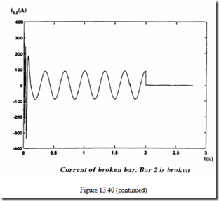
• The case of faulty bars is handled by increasing the resistance of that (those) bar (Rb) a few orders of magnitude.
• When an end ring segment is broken, the corresponding Re/Nr term in the resistance matrix is increased a few orders of magnitude (both along the diagonal and along its vertical and horizontal direction in the last row and column, respectively.
In Reference [33], a motor with the following data was investigated:
Rs = 10 Ω, Rb = Re = 155 µΩ, Lls = 0.035 mH, Lms = 378 mH, W1 = 340 turns/phase, Kw1 = 1, Nr = 30 rotor slots, p1 = 2 pole pairs, Le = Lb = 0.1 µH, Lsr = 0.873 mH, τ = 62.8 mm (pole pitch), L = 66 mm (stack length), g = 0.375 mm, Kc = 1, Ks = 0, J = 5.4⋅10-3 Kgm2, f = 50 Hz, VL = 380 V, Pn = 736 W, I0 = 2.1 A.
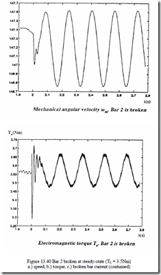
Numerical results for bar 2 broken (Rb2 = 200Rb) with the machine under load TFor the ring segment 3 broken (RL = 3.5 Nm are shown in (Figure 13.40e3 = 10)3. Re/Nr), the speed and torque are given in Figure 13.41 [33].
• Small pulsations in speed and torque are caused by a single bar or end ring segment faults.
• A few broken bars would produce notable torque and speed pulsations. Also, a 2Sf1 frequency component will show up, as expected, in the stator phase currents.
The transients of IM have also been approached by FEM, specifically by time stepping coupled FEM circuit (or state space) models. [35, 36] The computation time is still large, but the results are getting better and better as new contributions are made. The main advantage of this method is the possibility to account for most detailed topological aspects and non-linear material properties. Moreover, coupling the electromagnetic to thermal and mechanical modeling seems feasible in the near future.


