Power Amplifier Classes
For a long time the only amplifier classes relevant to high-quality audio were Class-A and Class-AB. This is because valves were the only active devices, and Class-B valve amplifiers generated so much distortion that they were barely acceptable, even for public address purposes. All amplifiers with pretensions to high fidelity operated in push–pull Class-A.
Solid state gives much more freedom of design; all of the following amplifier classes have been exploited commercially. Unfortunately, there will only be space to deal in detail in this book with A, AB, and B, although this certainly covers the vast majority of solid-state amplifiers. Plentiful references are given so that the intrigued can pursue matters further.
Class-A
In a Class-A amplifier, current flows continuously in all the output devices, which enables the nonlinearities of turning them on and off to be avoided. They come in two rather different kinds, although this is rarely explicitly stated, which work in very different ways. The first kind is simply a Class-B stage (i.e., two emitter–followers working back to back) with the bias voltage increased so that sufficient current flows for neither device to cut off under normal loading. The great advantage of this approach is that it cannot abruptly run out of output current; if the load impedance becomes lower than specified, then the amplifier simply takes brief excursions into Class-AB, hopefully with a modest increase in distortion and no seriously audible distress.
The other kind could be called a controlled-current source type, which is, in essence, a single emitter–follower with an active emitter load for adequate current sinking. If this latter element runs out of current capability, it makes the output stage clip much as if it had run out of output voltage. This kind of output stage demands a very clear idea of how low an impedance it will be asked to drive before design begins.
Valve textbooks contain enigmatic references to classes of operation called AB1 and AB2; in the former, grid current did not flow for any part of the cycle, but in the latter, it did. This distinction was important because the flow of output-valve grid current in AB2 made the design of the previous stage much more difficult.
AB1 or AB2 has no relevance to semiconductors, for base current in BJT always flows when a device is conducting, whereas gate current in power FET never does, apart from charging and discharging internal capacitances.
Class-AB
This is not really a separate class of its own, but a combination of A and B. If an amplifier is biased into Class-B and then the bias increased further, it will enter AB. For outputs below a certain level, both output devices conduct and operation is Class-A. At higher levels, one device will be turned completely off as the other provides more current, and the distortion jumps upward at this point as AB action begins. Each device will conduct between 50 and 100% of the time, depending on the degree of excess bias and the output level.
Class-AB is less linear than either A or B, and in my view its only legitimate use is as a fallback mode to allow Class-A amplifiers to continue working reasonably when faced with low-load impedance.
Class-B
Class-B is by far the most popular mode of operation, and probably more than 99% of the amplifiers currently made are of this type. Most of this book is devoted to it, so no more is said here.
Class-C
Class-C implies device conduction for significantly less than 50% of the time and is normally only usable in radio work, where an LC circuit can smooth out the current
pulses and filters harmonics. Current-dumping amplifiers can be regarded as combining Class-A (the correcting amplifier) with Class-C (the current-dumping devices); however, it is hard to visualize how an audio amplifier using devices in Class-C only could be built.
Class-D
These amplifiers continuously switch the output from one rail to the other at a supersonic frequency, controlling the mark/space ratio to give an average representing the instantaneous level of the audio signal; this is alternatively called pulse width modulation. Great effort and ingenuity have been devoted to this approach, for the efficiency is, in theory, very high, but the practical difficulties are severe, especially so in a world of tightening EMC legislation, where it is not at all clear that a 200-kHz high-power square wave is a good place to start. Distortion is not inherently low5and the amount of global NFB that can be applied is severely limited by the pole due to the effective sampling frequency in the forward path. A sharp cutoff low-pass filter is needed between amplifier and speaker to remove most of the RF; this will require at least four inductors (for stereo) and will cost money, but its worst feature is that it will only give a flat frequency response into one specific load impedance. The technique now has a whole chapter of this book to itself. Other references to consult for further information are Goldberg and Sandler6 and Hancock.7
Class-E
An extremely ingenious way to operate a transistor is to have either a small voltage across it or a small current through it almost all the time; in other words, the power dissipation is kept very low.8 Regrettably, this is an RF technique that seems to have no sane application to audio.
Class-F
There is no Class-F, as far as I know. This seems like a gap that needs filling.
Class-G
This concept was introduced by Hitachi in 1976 with the aim of reducing amplifier power dissipation. Musical signals have a high peak/mean ratio, spending most of this at low levels, so internal dissipation is much reduced by running from low-voltage rails for small outputs, switching to higher rails current for larger excursions.
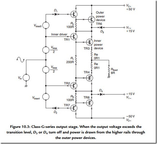
The basic series Class-G with two rail voltages (i.e., four supply rails, as both voltage are ±) is shown in Figure 10.3.9,11 Current is drawn from the lower ±V1 supply rails whenever possible; should the signal exceed ±V1, TR6 conducts and D3 turns off, so the output current is now drawn entirely from the higher ±V2 rails, with power dissipation shared between TR3 and TR6. The inner stage TR3, TR4 is usually operated in Class-B, although AB or A is equally feasible if the output stage bias is suitably increased. The outer devices are effectively in Class-C as they conduct for significantly less than 50% of the time.
In principle, movements of the collector voltage on the inner device collectors should not significantly affect the output voltage, but in practice, Class-G is often considered to have poorer linearity than Class-B because of glitching due to charge storage in commutation diodes D3, D4. However, if glitches occur they do so at moderate power, well displaced from the crossover region, and so appear relatively infrequently with real signals.
An obvious extension of the Class-G principle is to increase the number of supply voltages. Typically the limit is three. Power dissipation is further reduced and efficiency increased as the average voltage from which the output current is drawn is kept closer to the minimum. The inner devices operate in Class-B/AB as before, and the middle devices are in Class-C. The outer devices are also in Class-C, but conduct for even less of the time.
To the best of my knowledge, three-level Class-G amplifiers have only been made in shunt mode, as described later, probably because in series mode the cumulative voltage drops become too great and compromise the efficiency gains. The extra complexity is significant, as there are now six supply rails and at least six power devices, all of which must carry the full output current. It seems most unlikely that this further reduction in power consumption could ever be worthwhile for domestic hi-fi.
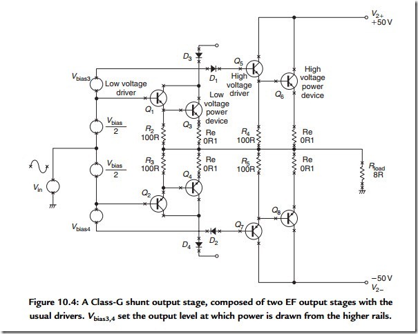
A closely related type of amplifier is Class-G shunt.10 Figure 10.4 shows the principle; at low outputs, only Q3, Q4 conduct, delivering power from the low-voltage rails. Above a threshold set by Vbias3 and Vbias4, D1 or D2 conduct and Q6, Q8 turn on, drawing current from the high-voltage rails, with D3, 4 protecting Q3, 4 against reverse bias. The conduction periods of the Q6, Q8 Class-C devices are variable, but inherently less than 50%. Normally the low-voltage section runs in Class-B to minimize dissipation. Such shunt Class-G arrangements are often called “commutating amplifiers.”
Some of the more powerful Class-G shunt PA amplifiers have three sets of supply rails to further reduce the average voltage drop between rail and output. This is very useful in large PA amplifiers.
Class-H
Class-H is once more basically Class-B, but with a method of dynamically boosting the single supply rail (as opposed to switching to another one) in order to increase efficiency.12 The usual mechanism is a form of bootstrapping. Class-H is used occasionally to describe Class-G as described earlier; this sort of confusion we can do without.
Class-S
Class-S, so named by Doctor Sandman,13 uses a Class-A stage with very limited current capability, backed up by a Class-B stage connected so as to make the load appear as a higher resistance that is within the capability of the first amplifier.
The method used by the Technics SE-A100 amplifier is extremely similar.14 I hope that that this necessarily brief catalogue is comprehensive; if anyone knows of other bona fide classes I would be glad to add them to the collection. This classification does not allow a completely consistent nomenclature; for example, quad-style current dumping can only be specified as a mixture of Class-A and -C, which says nothing about the basic principle of operation, which is error correction.
Variations on Class-B
The solid-state Class-B three-stage amplifier has proved both successful and flexible, so many attempts have been made to improve it further, usually by trying to combine the efficiency of Class-B with the linearity of Class-A. It would be impossible to give a comprehensive list of the changes and improvements attempted, so I give only those that have been either commercially successful or particularly thought provoking to the amplifier-design community.
Error-Correcting Amplifiers
This refers to error-cancellation strategies rather than the conventional use of NFB. This is a complex field, for there are at least three different forms of error correction, of which the best known is error feedforward as exemplified by the ground-breaking Quad 405.15 Other versions include error feedback and other even more confusingly named techniques, some of which turn out on analysis to be conventional NFB in disguise. For a highly ingenious treatment of the feedforward method, see Giovanni Stochino.16
Nonswitching Amplifiers
Most of the distortion in Class-B is crossover distortion and results from gain changes in the output stage as the power devices turn on and off. Several researchers have attempted to avoid this by ensuring that each device is clamped to pass a certain minimum current at all times.17 This approach has certainly been exploited commercially, but few technical details have been published. It is not intuitively obvious (to me, anyway) that stopping the diminishing device current in its tracks will give less crossover distortion.
Current-Drive Amplifiers
Almost all power amplifiers aspire to be voltage sources of zero output impedance. This minimizes frequency response variations caused by the peaks and dips of the impedance curve and gives a universal amplifier that can drive any loudspeaker directly.
The opposite approach is an amplifier with a sufficiently high output impedance to act as a constant-current source. This eliminates some problems, such as rising voice-coil resistance with heat dissipation, but introduces others, such as control of the cone resonance. Current amplifiers therefore appear to be only of use with active crossovers and velocity feedback from the cone.18 It is relatively simple to design an amplifier with any desired output impedance (even a negative one) and so any compromise between voltage and current drive is attainable. The snag is that loudspeakers are universally designed to be driven by voltage sources, and higher amplifier impedances demand tailoring to specific speaker types.19
The Blomley Principle
The goal of preventing output transistors from turning off completely was introduced by Peter Blomley in 197120; here the positive/negative splitting is done by circuitry ahead of the output stage, which can then be designed so that a minimum idling current can be separately set up in each output device. However, to the best of my knowledge this approach has not yet achieved commercial exploitation.
Geometric Mean Class-AB
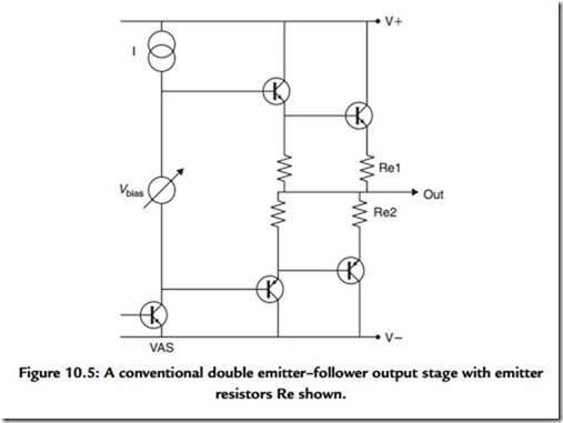
The classical explanations of Class-B operation assume that there is a fairly sharp transfer of control of the output voltage between the two output devices, stemming from an equally abrupt switch in conduction from one to the other. In practical audio amplifier stages this is indeed the case, but it is not an inescapable result of the basic principle. Figure 10.5 shows a conventional output stage, with emitter resistors Re1, Re2 included to increase quiescent-current stability and allow current sensing for overload protection; to a large extent, these emitter resistances make classical Class-B what it is.
However, if the emitter resistors are omitted and the stage biased with two matched diode junctions, then the diode and transistor junctions form a translinear loop21 around which the junction voltages sum to zero. This links the two output transistor currents Ip, In in the relationship In * Ip = constant, which in op-amp practice is known as geometric-mean Class-AB operation. This gives smoother changes in device current at the crossover point, but this does not necessarily mean lower THD. Such techniques are not very practical for discrete power amplifiers; first, in the absence of the very tight thermal coupling between the four junctions that exists in an IC, the quiescent-current stability will be atrocious, with thermal runaway and spontaneous combustion a near certainty. Second, the output device bulk emitter resistance will probably give enough voltage drop to turn the other
device off anyway, when current flows. The need for drivers, with their extra junction drops, also complicates things.
A new extension of this technique is to redesign the translinear loop so that 1/In + 1/Ip = constant; this is known as harmonic-mean AB operation.22 It is too early to say whether this technique (assuming it can be made to work outside an IC) will be of use in reducing crossover distortion and thus improving amplifier performance.
Nested Differentiating Feedback Loops
This is a most ingenious, but conceptually complex technique for significantly increasing the amount of NFB that can be applied to an amplifier (see Cherry23).


