The Three-Stage Architecture
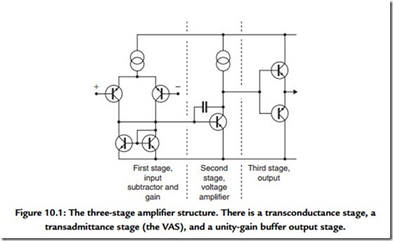
The vast majority of audio amplifiers use the conventional architecture, shown in Figure 10.1. There are three stages, the first being a transconductance stage (differential
voltage in, current out), the second a transimpedance stage (current in, voltage out), and the third a unity-voltage-gain output stage. The second stage clearly has to provide all the voltage gain and I have therefore called it the voltage-amplifier stage or VAS. Other authors have called it the predriver stage but I prefer to reserve this term for the first transistors in output triples. This three-stage architecture has several advantages, not least being that it is easy to arrange things so that the interaction between stages is negligible. For example, there is very little signal voltage at the input to the second stage due to its current input (virtual-earth) nature, and therefore very little on the first stage output; this minimizes Miller phase shift and possible early effect in the input devices.
Similarly, the compensation capacitor reduces the second stage output impedance so that the nonlinear loading on it due to the input impedance of the third stage generates less distortion than might be expected. The conventional three-stage structure, familiar though it may be, holds several elegant mechanisms such as this. Since the amount of linearizing global NFB available depends on amplifier open-loop gain, how the stages contribute to this is of great interest. The three-stage architecture always has a unity-gain output stage—unless you really want to make life difficult for yourself—and so the total forward gain is simply the product of the transconductance of the input stage and the transimpedance of the VAS, the latter being determined solely by the Miller capacitor Cdom, except at very low frequencies. Typically, the closed-loop gain will be between +20 and +30 dB. The NFB factor at 20 kHz will be 25 to 40 dB, increasing at 6 dB per octave with falling frequency until it reaches the dominant pole frequency P1, when it flattens out. What matters for the control of distortion is the amount of NFB available, rather than the open-loop bandwidth, to which it has no direct relationship. In my Electronics World Class-B design, the input stage gm is about 9 mA/V, and Cdom is 100 pF, giving an NFB factor of 31 dB at 20 kHz. In other designs I have used as little as 26 dB (at 20 kHz) with good results.
Compensating a three-stage amplifier is relatively simple; since the pole at the VAS is already dominant, it can be easily increased to lower the HF NFB factor to a safe level. The local NFB working on the VAS through Cdom has an extremely valuable linearizing effect.
The conventional three-stage structure represents at least 99% of the solid-state amplifiers built, and I make no apology for devoting much of this book to its behavior. I doubt if I have exhausted its subtleties.
Two-Stage Amplifier Architecture
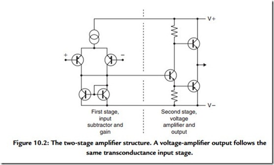
In contrast, the architecture shown in Figure 10.2 is a two-stage amplifier, with the first stage once again being more a transconductance stage, although now without a guaranteed low impedance to accept its output current. The second stage combines VAS and output stage in one block; it is inherent in this scheme that the VAS must double as a phase splitter as well as a generator of raw gain. There are then two quite dissimilar signal paths to the output, and it is not at all clear that trying to break this block down further will assist a linearity analysis. The use of a phase-splitting stage harks back to valve amplifiers; where it was inescapable as a complementary valve technology has, so far, eluded us.
Paradoxically, a two-stage amplifier is likely to be more complex in its gain structure than a three stage. The forward gain depends on the input stage gm, the input stage collector load (because the input stage can no longer be assumed to be feeding a virtual earth),
and the gain of the output stage, which will be found to vary in a most unsettling manner with bias and loading. Choosing the compensation is also more complex for a two-stage amplifier, as the VAS/phase splitter has a significant signal voltage on its input and so the usual pole-splitting mechanism that enhances Nyquist stability by increasing the pole
frequency associated with the input stage collector will no longer work so well. (I have used the term Nyquist stability or Nyquist oscillation throughout this book to denote oscillation due to the accumulation of phase shift in a global NFB loop, as opposed to local parasitics, etc.)
The LF feedback factor is likely to be about 6 dB less with a 4-Ω load due to lower gain in the output stage. However, this variation is much reduced above the dominant pole frequency, as there is then increasing local NFB acting in the output stage.
Two-stage amplifiers are not popular; I can quote only two examples, Randi3 and Harris.4 The two-stage amplifier offers little or no reduction in parts cost, is harder to design, and, in my experience, invariably gives a poor distortion performance.

