Phase Shifting the SCR
The SCR can control all of the positive waveform through the use of phase shifting. As the term implies, phase shifting means to shift the phase of one thing in reference to another. In this instance, the voltage ap- plied to the gate must be shifted out of phase with the voltage applied to the anode. Although there are several methods used for phase shifting an SCR, it is beyond the scope of this text to cover all of them. The basic principles are the same for all of the methods, however, so only one method is covered.
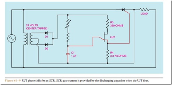
To phase shift an SCR, the gate circuit must be un- locked or separated from the anode circuit. The circuit shown in Figure 61– 9 will accomplish this. A 24 volt, center-tapped transformer is used to isolate the gate circuit from the anode circuit. Diodes Dl and D2 are used to form a two-diode type of full-wave rectifier
to operate the UJT circuit. Resistor R1 is used to determine the pulse rate of the UJT by controlling the charge time of capacitor C1. Resistor R2 is used to limit the current through the emitter of the UJT if resistor R1 is adjusted to 0 ohms. Resistor R3 limits current through the base 1 – base 2 section when the UJT turns on. Resistor R4 permits a voltage spike or pulse to be produced across it when the UJT turns on and discharges capacitor C1. The pulse produced by the discharge of capacitor C1 is used to trigger the gate of the SCR.
Since the pulse of the UJT is used to provide a trigger for the gate of the SCR, the SCR can be fired at any time regardless of the voltage applied to the anode. This means that the SCR can now be fired as early or late during the positive half cycle as desired because the gate pulse is determined by the charge rate of capacitor C1. The voltage across the load can now be adjusted from 0 to the full applied voltage.
Related posts:
Incoming search terms:
- phase shifting ckt using scr in polyphase
- phase shifting using scr in polyphase circuits
- SCR LOAD CONTROL CIRCUIT
- phase shifting an scr
- phase shift triggering of scr
- Phase shifting using SCRs in polyphase ckt
- Description phase shift triggering
- polyphase shifting using scr in polyphage circuit
- scr phase shift control project
- triggering by phase shifting
- ujt phase shifter
- ujt triggering circuit
- phase shifting using SCR in polyphase circuit
- phase shifting using scr in poly phase ckt
- phase shifting of scr
- lr phase shift control
- phase shift control scr
- phase shift control using scr
- phase shift controlling of scr
- phase shift in scr
- phase shift triggering circuit for scr
- Phase shift triggering Definition
- phase shifter for scr
- ujt triggring
