Photoresistors and photoconductors
Many materials have a resistance value that will change when light strikes the material. The theory behind this effect is that these materials are semi- conductors that in their normal state have few free electrons or holes. The effect of light is to separate electrons from holes and so allow both types of particles to move through the material and carry current. Since a definite amount of energy is needed in order to separate an electron from a hole, the size of the light quantum is important, but it is not difficult to find materials for which the amount of energy is small, corresponding to a
quantum of infrared light. Since, in addition, the materials are comparatively easy to prepare in a practical form, the use of photoresistive or photo- conductive materials is very common. The two names should really be synonymous, but some lists show devices under one name or the other.
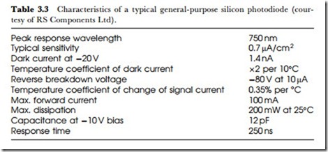
Because of the physical action, the effect is always that the material has high resistance in the absence of light, and the resistance drops when the material is illuminated. The effect of light on a photodiode is also one of reducing resistance, in this case the resistance of a reverse-biased diode, and the reason for the use of a separate name is that the manufacturing process for photodiodes is the same as is used for other semiconductor devices.
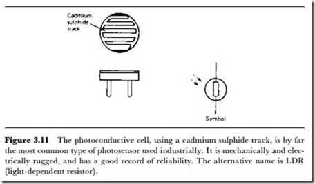
The most common form of photoconductive cell is the cadmium sulphide cell, named after the material used as a photoconductor. This is often referred to as an LDR (light-dependent resistor). The cadmium sulphide is deposited as a thread pattern on an insulator, and since the length of this pattern affects the sensitivity, the shape is usually a zigzag line (Figure 3.11). The cell is then encapsulated in a transparent resin or encased in glass to protect the cadmium sulphide from contamination by the atmosphere.
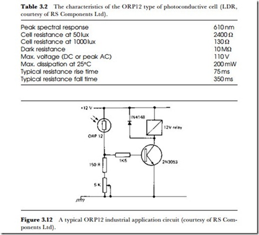
The cell is very rugged and can withstand a considerable range of tem- peratures, either in storage or during operation. The voltage range can also be considerable, particularly when a long track length of cadmium sulphide has been used, and this type of cell is one of the few devices that can be used with an AC supply. Table 3.2 shows typical specifications for a popular type of cell, the ORP12. The peak spectral response of 610 nm cor- responds to a colour in the yellow-orange region, and the dark resistance of 10 MQ will fall to a value in the ohms to kilohms region upon illumina- tion. The sensitivity is not quoted as a single figure because the change of resistance plotted against illumination is not linear. The maximum voltage
rating of 100 V DC or AC peak allows a considerable latitude in power supplies, subject only to the 200 mW maximum dissipation. A typical spectral response graph was illustrated earlier in Figure 3.5.
The peak response at the yellow-orange region of the spectrum makes this LDR particularly useful for detecting the presence of a flame. The ORP12 finds its main application in control units, in particular for vaporizing oil-fired boilers (so that oil is cut off if the flame is extinguished) and in fire detecting equipment. In such applications, the main drawback of the LDR, which is a comparatively long response time, is not a drawback. The typical resistance fall time, meaning the time for the resistance to reach its final value when the cell is illuminated, is 350 ms; the resistance rise time when illumination is cut off is typically 75 ms. These times are reasonable when compared to the operating times of the relays that the ORP12 is so often used to operate, but they make any type of use with modulated light beams out of the question. A typical circuit using the ORP12 is illustrated in Figure 3.12.


