Split-Phase Motors
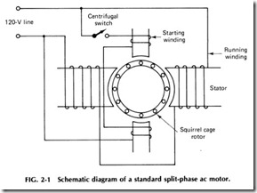
Split-phase motors are fractional hp units which use an auxiliary winding on the stator to aid in starting the motor until it reaches its proper rota tion speed. See Fig. 2-1. This type of motor finds uses in small pumps, oil burners, automatic washers, and other household appliances.
In general, the split-phase motor consists of a housing, a laminated iron core stator with embedded windings forming the inside of the cylindrical housing, a rotor which is made up of copper bars set in slots in an iron core and connected to each other by copper rings around both ends of the core and plates which are bolted to the housing and contain the bear ings which support the rotor shaft, and a centrifugal switch inside the housing. This type of rotor is often called a squirrel cage rotor since the configuration of the copper bars resembles an actual cage. Such motors
have no windings as such, and a centrifugal switch is provided to open the circuit to the starting winding when the motor reaches running speed.
To understand the operation of a split-phase motor, look at the wiring diagram in Fig. 2-1. Current is applied to the stator windings, both the main winding and the starting winding which is in parallel with it,through the centrifugal switch. The two windings set up a rotating mag netic field, and this field sets up a voltage in the copper bars of the squir rel cage rotor. Because these bars are shortened at the ends of the rotor, current flows through the rotor bars. The current-carrying rotor bars then react with the magnetic field to produce motor action. When the rotor is turning at the proper speed, the centrifugal switch cuts out the starting winding since it is no longer needed.
CENTRIFUGAL SWITCH
The centrifugal switch, located inside the motor, consists of two main parts: a stationary part and a rotating part. The former is located on the front end plate of the motor and has two contacts, similar to a conven tional single-pole switch. The latter, or rotating part, is located on the rotor as shown in Fig. 2-2.
When the motor is not running, the two contacts on the stationary part of the centrifugal switch are kept closed by the pressure of the rotat ing part. However, at about 75o/o of the motor’s full speed, the rotating part releases its pressure against the contacts and causes them to open, disconnecting the starting winding from the circuit.
The stationary part of some centrifugal switches consists of two copper semicircular segments that are insulated from each other and mounted on the inside of the front end plate. The rotating part has three
copper fingers that ride around the stationary segments while the motor is starting. While the motor is at a standstill, the segments are shortened by the copper fingers, causing the starting winding to be included in the motor circuit. When the motor reaches approximately 75o/o of its full speed, the centrifugal force causes the fingers to be lifted from the seg ments, disconnecting the starting winding from the circuit.
SQUIRREL-CAGE ROTOR
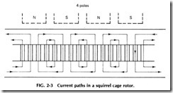
The rotors of induction motors are either wound or of the squirrel cage type. The type used on split-phase motors is of the latter type. It consists of conducting bars connected rigidly together by conducting rings. The voltage induced in each bar is seldom more than 10 V, so that insulation between the bars and core is not always necessary. The bars under each pole are in parallel with the currents under adjacent poles in opposite directions. The current flowing out from the bars under one pole passes into the end ring and, dividing equally, returns to the other side of the core through the bars under each of the two adjacent half poles as shown in Fig. 2-3.
Since the squirrel-cage rotor is symmetrical and has no connections within itself- which determine the relative directions of current flow in the rotor- the currents induced in the bars and the number of poles pro duced are determined only by the stator winding. This enables a squirrel cage rotor to operate in any primary of the correct mechanical dimen sions and will run at the speed of the stator field minus the slip. However, the starting torque, which is dependent on the rotor resistance, will not be the same when the rotor is used in stators with different numbers of poles, since the current paths in the rotor winding are changed, altering the effective resistance of the secondary.
The rotor resistance is made up of bar and end-ring resistance. Since the bars under each pole are in parallel, the bar resistance per short circuit path will be less as the number of poles is decreased and the num ber of bars per pole increases. But the number of parallel paths decreases as the bars per pole increase. Since these two effects will then balance each other, the equivalent bar resistance does not change as the number of poles is varied.
Changing the number of primary poles, however, changes the effec tive resistance of the portion of the winding which is included in the end rings. The cross-sectional area of the ring is constant, while the length of the ring included by each path decreases and the number of parallel paths increases as the number of poles is increased. Therefore, the portion of the rotor resistance due to the end rings is approximately inversely proportional to the square of the number of poles.
In general, the greater the resistance of a squirrel-cage winding, the greater is the starting torque and the slower the speed corresponding to any torque. High-resistance windings for slow-speed, multipolar ma chines are made by using bars of small cross section or of low conductiv ity and rings made of a low-conductivity alloy.
In actual practice, the size and number of bars and the size of the rings are usually standardized, so that the required total resistance is ob tained by choosing different combinations of available components. Therefore, no definite percentage of the total resistance is put in the bar or ring. For this reason, one motor can have its secondary resistance, and consequently its starting torque, increased by machining the end rings, while another motor may show but little increase in-torque after machin ing off a large portion of the rings.
SPLIT-PHASE MOTOR TROUBLES
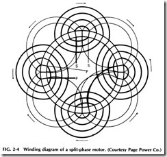
When a split-phase motor fails to operate properly, a definite procedure should be followed in determining the repairs necessary to put it into good condition to operate properly. To do so means performing a series of tests to discover the exact trouble. These tests should quickly show if the motor needs only minor repairs, such as new bearings, or if a partial or complete overhaul is in order. See Fig. 2-4.
FAlLURE TO START
1. No voltage: Use a voltmeter to check for proper voltage at the motor terminals. If the readings indicate ZERO voltage, check volt age, check for blown fuses or a tripped circuit breaker.
2. Low voltage: Take a reading at the motor terminals with the switch closed. This voltage should be within 10% of the rated name plate voltage. Overloaded transformers or circuits can cause a low voltage condition.
3. Faulty centrifugal switch: Remove the inspection plate in the front end bracket to observe the switch operation as the circuit is energized. If the disc does not hold the switch in the closed position when the motor is standing still, the motor cannot start; the end play washers may need adjusting. Check the contact points for dirt and foreign matter. Also check for clogged weights and a weak spring.
4. Open overload-protection device: If the motor is equipped with a built-in overload-protection device, let the motor cool before try ing to start it. If this fails, remove the cover plate on the end bracket on which the switch is mounted and see if the switch contacts are closed. If the switch is stuck, remove and repair.
5. Grounded field: If the motor overheats or produces a shock when touched or the output power at idle is excessive, test for a grounded field by placing the leads of a continuity tester between the field leads and the frame. If the field is grounded, repair or replace the motor.
6. Open field: Apply a current to both the starting and running windings separately through a test-lamp circuit. However, do not leave the windings connected too long while the rotor is stationary. If either winding is open, repair or replace the motor.
7. Shorted field: If the motor draws excessive current and at the same time lacks sufficient torque, overheats, or hums, a shorted field is indicated. The motor must be repaired or replaced.
8. Faulty end play: Some split-phase motors have steel-enclosed cork washers at each end of the motor to cushion the end thrust. Ex cessive end thrust, heat, or hammering on the shaft can destroy the washers and interfere with the operation of the cutout-switch mech anism. If necessary, install new end-thrust cushion-bumper assem blies. The end play should be adjusted so that the cutout switch is closed at standstill and open when the motor is operating.
9. Excessive load· This may be determined by comparing the in put current with the current rating on the nameplate. Excessive load may prevent the motor from reaching the speed at which the governor acts, thereby causing the phase winding to become over heated and burn out.
10. Tight bearings: Turn the armature by hand to determine if the bearings are too tight. If they are stiff and tight, add an oil that has been specified by the manufacturer. If this procedure does not work, replace the bearings.
LESS THAN SATISFACTORY OPERATION
1. Motor runs hot: Check for a grounded or shorted field, tight bearing, faulty centrifugal switch, wring voltage, or excessive load.
2. Motor does not reach full speed· Perform the same check as in test 1.
3. Excessive bearing wear: Check belt tension and alignment. Check for dirty, incorrect, or insufficient oil. If bearings are clogged with dirt or other foreign matter, clean them thoroughly. Worn bearings should be replaced.
4. Excessive noise: Check for worn bearings and excessive end play. If necessary, add additional end-play washers. Check for loose motor parts, hold-down bolts, or pulley; bad alignment, worn belts, sprung shafts, or unbalanced rotor; and/or burrs on the shaft shoulders.
5. Motor produces shock: Check for grounded stator; cushion mounted motors have a ground strip that carries static electricity across the rubber mounting to ground. If the static charge is re tained, the strip may be broken, or there may be poor connections present. The frames of all motors should be grounded.
6. Rotor rubs stator: Clean burrs and dirt from both the rotor and the stator. Check for worn bearings.
7. Radio and TV interference: Check for poor ground connections. Static electricity generated by the motor belts may cause noises if the motor is not thoroughly grounded. Check for loose contacts in the switch, the fuses, and/or the starter.
In performing the preceding tests, the following steps may prove to be useful and save considerable time:
• Carefully examine the outside of the motor housing to detect any broken or cracked parts- such as broken end plates or a bent shaft. Remove the cover plate and inspect for burned motor leads.
• Check for bearing trouble by moving the shaft up and down in the bearing. Any movement in either direction indicates a worn bearing.
Turn the rotor by hand and observe the freedom of movement. A shaft that does not rotate freely is an indication of severe prob lems- either bad bearings, a bent shaft, or an improperly assembled motor. If any of these problems exists, the motor should run hot and trip the overload protective devices.
• Examine the connection box carefully to see if any bare leads (either motor or line) are touching the motor frame. Also check to see if the enternal wires are making contact with the iron cores of the rotor or stator. Use a test meter here.
• If all the preceding tests check out favorably, connect the power lines to the motor terminals and see if the motor runs. If there are in ternal problems, usually the overcurrent device will trip or blow, the windings may smoke, or the motor may rotate slowly or noisily. Furthermore, the rotor may not turn at all; rather, humming may be heard. Such symptoms always indicate internal problems. If prob lems are evident, the motor should be disassembled and tested more carefully as described elsewhere in this book.


