Carter Carburetors
VF SERIES
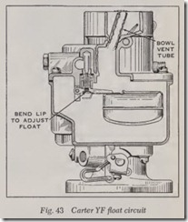
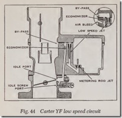
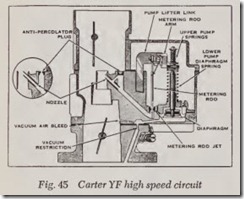
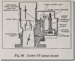
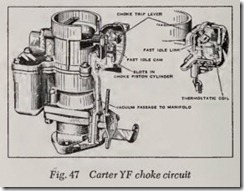
The YF Series is a single barrel carburetor combining the basic features of the fundamental carburetor previously described with several new features. These include a diaphragr:n type acceler ating pump, a bowl vent tube to maintain the correct air-fuel ratio at all times regardless of re striction in the air cleaner due to dirt. It also has a diaphragm operated metering rod, both vacuum and mechanically controlled. Figs. 43 to 47 show the construction of the various circuits.
Mechanical Metering Rod Action
Fig. 45. During part throttle operation, mani fold vacuum pulls the diaphragm assembly down, holding the metering rod arm against the pump lifter link. Movement of the metering rod will then be controlled by the pump lifter link, which is connected to the throttle shaft. This is true at all times when the vacuum under the diaphragm is strong enough to overcome the tension of the lower pump diaphragm spring. The upper pump spring serves as a bumper upon deceleration and a delayed action spring on acceleration.
Vacuum Metering Rod Action
Under any operating condition, when the ten sion of the lower pump diaphragm spring over comes the pull of vacuum under the diaphragm, the metering rod will move toward the wide open throttle or power position.
The restriction and air bleed in the vacuum passage provide a lower and more uniform vacuum condition in the chamber below the dia phragm.
Anti-Percolator
To prevent vapor bubbles in the nozzle passage and low-speed well caused by heat from forcing fuel out of the nozzle, anti-percolator passages, calibrated plugs and bushings are used, Fig. 45.
Their purpose is to vent the vapors and relieve the pressure before it is sufficient to push the fuel out of the nozzle and into the intake manifold.
Anti-percol ator plugs, bu shings and the m ain nozzle are permanently installed and must not be removed in service.
Acceler ating Pump Circuit
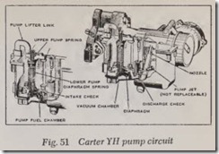
Fig. 46. The accelera ting pump circuit provides a measured amount of fuel, which is necessary to insure smooth engine operation for acceleration at speeds below about 30 miles per hour.
Pump action is controlled both mechani cally and by manifold vacuum in the same manner as the metering rod. When the throttle is closed, the diaphragm moves downward and fuel is drawn into the fuel pump chamber.
There are three types of intake systems used on YF carburetors: intake passage, intake check valve, intake passage plus an intake check valve.
When the diaphragm moves downward,’ th e discharge check is seated. When the throttle is opened, the diaphragm moves upward, forcing fuel out through the discharge passage, past the discharge check, and out of t e pump jet. The pump discharges through the main nozzle on mod els wh ere no pump jet is used. On models with an intake passage , a measured amount of fuel is returned to the bowl through this passage. Carburetors that have only an intake check valve do not discharge fuel back into the bowl. When the diaphragm m oves upward, the intake check (where used) must seat.
If the throttle is opened suddenly, the upper pump spring will be compressed, resulting in a smooth er pump disch arge of longer duration.
Manifold vacuum is applied to the underside of the diaphr agm at all times th e engine is in opera tion. Wh en manifold vacuum decreases to the point where the lower pump diaphragm spring overcom es th e pull of vacuum, the diaphragm moves upward and a pump discharge results.
The pump j et is pressed into the casting during man uf actur e and must not be removed in service.
YH SERIES
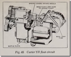
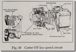
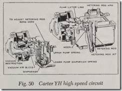
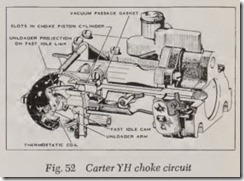
The YH carburetor may be compar ed with the YF unit with the circuits rearranged to operate in a horizontal or sidedraft position . It has the five conventional circuits as are used in YF carbu ret ors. Figs. 48 through 52 show the construction
WCFB SERIES
The WCFB carburetor is basically two dual carburetors contained in one assembly. The sec tion containing the metering rods, accelerating pump and choke is termed the primary side of the carburetor while the other section is called the secondary side. It has five conventional circuits, the same as other Carter carburetors. They are:
Two float circuits. Two low speed circuits. Two high speed circuits.
One pump circuit.
One choke circuit.
Float Circuits
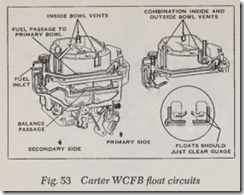
Fig. 53. The primary and secondary bowls arc separated by a partition. The fuel line connection is above the secondary needle valve and seat. Fuel is supplied to the primary needle and seat through the passage in the bowl cover.
The bowls are vented to the inside of the air horn, and (on certain models) also to atmosphere. Bowl vents are calibrated to provide proper air pressure above the fuel at all times.
A connecting passage along the outside of the body effects a balance of the fuel levels and air pressures between the two bowls.
Low Speed Circuits
Fuel for idle and early part throttle operation is metered through the low speed circuits.
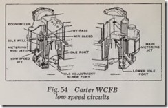
Gasoline enters the idle wells through the metering rod jets on the primary side of the carburetor and through the main metering jets on the secondary side, Fig. 54.
The low speed jets measure the amount of fuel for idle and early part throttle operation. The air by-pass passages, economizers and idle air bleeds are carefully calibrated and serve to break up the liquid fuel and mix it with air as it moves through the passages to the idle ports and idle adjustment screw ports. There are no idle adjustment screws on the secondary side of the carburetor.
The idle ports are slot shaped. As the throttle valves are opened, more of the idle ports are un covered, allowing a greater quantity of fuel-air mixture to enter the carburetor bores. The secon dary throttle valves remain closed at idle.
The vapor vent ball check, operated by the arm on the countershaft, provides a vent for fuel vapors to escape from the carburetor bowls to the outside at idle and when the engine is not in oper ation.
High Speed Circuits
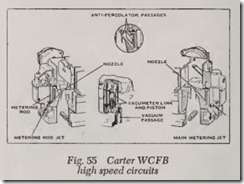
Fuel for pali throttle and full throttle operation is supplied through the high speed circuits, Fig. 55.
Primary Side-The position of the metering rods in the mei:ering rod jets controls the amount of fuel flowing in the high speed circuit of the primary side of the carburetor. The position of the metering rods is dual controlled-mechanically by movement of the throttle, and by manifold vacuum applied to the vacuum piston on the vacumeter link.
Secondary Side-Fuel for the high speed circuit of the secondary side is metered at the main metering jets (no metering rods are used).
Throttle valu es in the secondary side remain closed until the primary throttle valves have been opened a pre-determined ainount. They arrive at wide open throttle position at the same time as the primary throttles. This is accomplished by linkage between the throttle levers. Certain models have offset throttle valves mounted above the secon dary throttle valves, which are called “auxiliary throttle valves.” Air velocity through the carbu retor controls the position of the auxiliary throttle valves. When the accelerator is fully depressed, only the primary high speed circuit “will function until there is sufficient air velocity to open the auxiliary throttle valves. When this occurs, fuel will also be supplied through the secondary high speed circuit.
Auxiliary throttle valves, or the secondary throttle valves on models without auxiliary valves, are locked closed during choke operation to insure faster cold engine starting.
Anti-Percolator
Fig. 55. To prevent the vapor bubbles in the nozzle passages and low speed wells, caused by heat forcing fuel out of the nozzles, anti-percolator passages and calibrated plugs and bushings are used. Their purpose is to vent the vapors and relieve the pressure before it is sufficient to push the fuel out of the nozzles and into the intake manifold. Anti-percolator plugs, bushings and main nozzles are permanently installed and must not be removed in service.
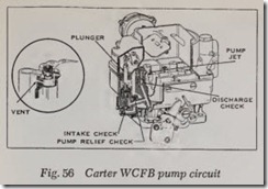
Pump Circuit
Fig. 56. This circuit is found only on the pri mary side of the carburetor. It provides a mea sured amount of fuel, which is necessary to insure smooth engine operation for acceleration at speeds below approximately 30 miles per hour.
When the throttle is closed, the pump plunger moves upward in its cylinder and fuel is drawn into the pump cylinder through the intake check. The discharge check is seated at this time to pre vent air being drawn into the cylinder. When the throttle is opened, the pump plunger moves downward, forcing fuel out through the discharge passage, past the discharge check, and out of the pump jets. When the plunger moves downward the intake check is closed, preventing fuel from being forced back into the bowl.
If the throttle is opened suddenly, the upper pump spring will be compressed by the plunger shaft telescoping, resulting in a smooth pump dis charge of longer duration.
At speeds above approximately 30 miles per hour, pump discharge is no longer necessary to insure smooth acceleration. When the throttle valves are opened a pre-determined amount, the pump plunger bottoms in the pump cylinder, eliminating pump discharge due to pump plunger movement at high speeds.
During high speed operation, a vacuum exists at the pump jets. To prevent fuel from being drawn through the pump circuit, the passage to the pump jets is vented by a cross passage to the carburetor bowl above the fuel level. This allows air instead of fuel to be drawn off the pump jets.
On certain models a pump relief check prevents excessive pressure in the discharge passage during acceleration.
