Mathematical Model
For constant speed control applications, the supply voltage and frequency are both constants. When the motor is at rest, the synchronous rotating field induces e.m.f.s at supply frequency in the stationary rotor. The rotor conductors are short circuited at each end and if the circuit is purely resistive, the current and e.m.f. distributions are identical. The torque contribution of each rotor conductor is proportional to the product of the conductor current and the local flux density. This is the optimum condition for the production of electromagnetic torque. If the rotor circuit is purely inductive, the resultant torque is zero. In practice, the rotor power factor is always greater than zero, and hence a motor torque is developed which causes the machine to run-up from the standstill in the same direction as the air-gap field.
At the synchronous speed, the torque becomes zero. Because of the mechanical and windage friction, the rotor always rotates at a speed smaller than the synchronous speed. If the motor is running at a speed n less than the synchronous speed n1, the difference, n1 − n, is called the slip speed of the machine and usually expressed as a fraction of the synchronous speed to give the fractional slip sℓ as
For normal loading conditions, it can be fairly accurately assumed that the air-gap flux is constant. The magnitude of the rotor e.m.f. is then proportional to the frac- tional slip sℓ. If the rotor runs in exact synchronism with the air-gap field, the in- duced e.m.f. is zero and the rotor develops zero torque. In practice, even on no load, a small motor torque is required to overcome windage and friction, and the motor runs at a speed which is slightly less than the synchronous speed. When the load is applied to the motor shaft, the speed drops further below synchronous speed and larger rotor currents are induced. When a rotor current flows, an additional compo- nent of stator current is induced. As in a transformer, this load component of stator current neutralizes the rotor m.m.f. and leaves the resultant air-gap flux practically unaltered, as previously assumed. With the above assumption, the torque developed by the motor can be written as
The rotor current and the stator current are related to each other with a constant factor. Therefore, like for DC motors the output torque can be assumed to be pro- portional to the stator current as
Where Kt is the constant of proportionality and I is the stator current. As will be discussed later, Eq. (6.4) is only valid for small range of motor operating point.
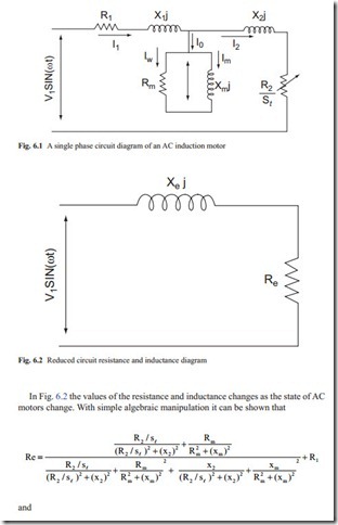
In order to obtain the voltage equation of an AC induction motor the complete characteristics of stator and rotor must be known. To simplify the analysis, the equivalent circuit diagram of an AC motor for one of the supply phase must be studied. This is necessary because to obtain a mathematical model, a linear relation between the applied voltage and the stator current must be found. Because of the interaction between the rotor and stator the circuit diagram is fairly complex. The circuit diagram for one phase is shown in Fig. 6.1.
In Fig. 6.1, R1 is the stator resistance, X1 = L1 ω is the stator reactance (ohms), R2 is the rotor resistance (ohms), X2 = L2 ω is the rotor reactance (ohms), Rm is the magnetizing resistance (ohms), Xm = Lm ω is the magnetizing reactance (ohms), sℓ is the slip ratio, and the resistance R2/sℓ resistance provide the equivalent back e.m.f. of DC motors.
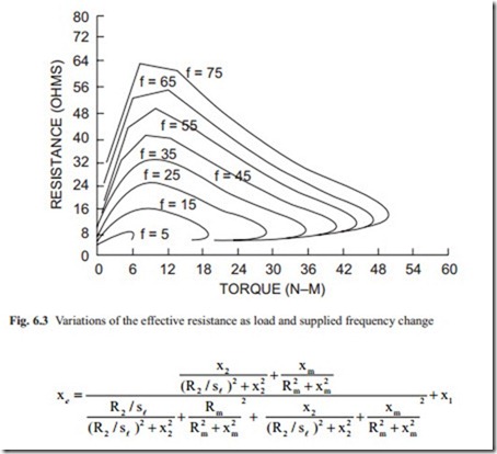
The circuit diagram of Fig. 6.1 can be reduced to a single resistance and reac- tance as shown in Fig. 6.2.
The above two equations give the equivalent resistance and inductance of AC mo- tors as the operating conditions of the motor changes. It shows that the effective resistance and inductance of the motor are function of slip ratio sℓ (torque) and the supplied frequency. To study the variations of resistance and inductance a 2.2 KW 3 phase induction AC motor is considered.
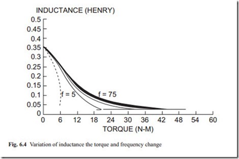
Figure 6.3 shows the variation of equivalent resistance as the torque is increased at various frequencies. It shows that at no load conditions the resistance is very low indicating that larger current will flow through the resistance of the motor. As the torque is increased, the resistance increases, reaching to a maximum and it reduces again at large applied torque. It also shows that at low supplied frequency the resistance reduces rapidly. This is the reason that at low frequency the amplitude of the voltage must be reduced to avoid excessive current flowing through the effective resistance of the motor windings.
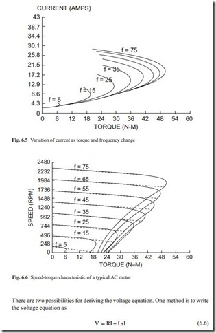
The equivalent inductance can also be calculated similar to calculation of the resistance. This is shown in Fig. 6.4. It shows that at low values of torque the inductance is very large and when the torque is increased the equivalent inductance reduces. The rate of the inductance reduction as torque increased is greater when the frequency is reduced. Both Figs. 6.3 and 6.4 show that there is an operating point for AC motors. It is also the point where the resistance and inductance have such
values that the motor generate sufficient torque to overcome the applied torque. The torque must not be very small so that the resistance is low and it should not be too large when the resistance is small. It would be interesting to calculate the current as the torque is increased.
It is possible to predict the variation of the current as the external torque in- creases from the variation of resistance and inductance. This is shown in Fig. 6.5. The figure shows that as the torque increases the current also increases. As the torque increases, the current almost linearly increases. At large values of current, the torque reduces rapidly. This is a disadvantage for AC servo motors. Therefore, the AC motors as mentioned previously do not have large starting torque. It would be interesting to observe speed-torque characteristic of AC motors. In the above discussion, it was shown that the equivalent resistance and inductance can be calculated from the data provided by manufacturers. Then the current can be calculated. Once the current is known, the torque can be calculated accordingly from the torque equation given above. This is shown in Fig. 6.5.
It can be seen that the speed-torque characteristic of AC motors is linear over a wide range of speed and torque. This is shown by the dotted line in Fig. 6.6. At large torque, the speed drops rapidly and the output torque also drops rapidly. This diagram must be provided by manufacturers. As the frequency (speed) reduces the output torque also reduces. The torque equation can be assumed linear and as previously stated it can be written as
Where s is the Laplace operator, and the resistance and inductance are highly non- linear. At different supply voltage and frequency both resistance and inductance change. At small variation from the operating point the resistance and inductance can be assumed to be constant. The remaining governing differential equation for the rotor and load can be written similar to the equations derived for DC servo mo- tors. Various operating conditions must be considered in order to study the stability and accuracy for velocity and position control applications.
The second method is to write the voltage equation similar to DC motors, as
![]() In Eq. (6.7) Cm is the voltage constant and accounts for the fact that as the speed of the motor increases the current reduces. In this case the average resistance and capacitance may be considered.
In Eq. (6.7) Cm is the voltage constant and accounts for the fact that as the speed of the motor increases the current reduces. In this case the average resistance and capacitance may be considered.
It should be stressed that the voltage equation is only an approximation and various values of the constants may be used to study the stability and accuracy of the complete servo system. AC motors for position and speed control applications is the subject of intensive research. The reader must keep an eye on the new development in this field.
Related posts:
Incoming search terms:
- torque equation of ac servo motor
- ac servo motor with equations
- torque formula for ac servo motor
- torque equation of servo motor
- ac servo motor mathematical model
- formula speed torque characteristic ac sarvo motar
- servo motor mathatamtical derivation
- relationship between torque and speed of ac servo motor
- relation bet torque and speed in AC servo motor
- 2 phase A C servometer torque equation
- modelling of ac servo
- servo motor torque equation
- speed - torque characteristics of AC servomotor used formaulaes
- speed and torque relationship expression of ac servo motor
- speed-torque derivation of ac servio motor
- torgue eguation of ac servo motor
- torque equation of AC servo
- torque equation of ac servo motor from equivalent circuit
- mathematical modelling of ac servo motor
- mathematical model of motor
- Mathematical equation of 2 phase ac servo motor
- Ac servo motor derivation
- ac servo motor equations
- ac servo motor equivalent circuit
- ac servo motor torque calculation
- ac servomotor 2 phase torqe expression
- derivation of torque of ac servo motor
- differential equation of ac servo motor
- equivalent circuit of ac servo motor
- equivalent ckt of ac servo motor
- expression between torque and speed of ac servo motor
- expression for relationship between speed and torque of ac servomotor
- expression for showing relationship between speed and torque ac servo motor
- formula for torqe in ac servomotor
- how calculate load current of ac servo motor
- torque formula for ac servomotor


