Dry Lining Boxes
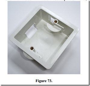
Figure 73 shows a single gang dry lining box. It is manufactured in three sizes to suit any board thickness from 10mm to 25mm. This box will accommodate plate switches, single sockets etc.
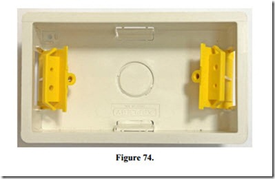
Figure 74 shows a twin dry lining box. It is also available in the three sizes mentioned above. This box will accommodate double plate switches and twin sockets. A deeper version is available for cooker switches and shaver sockets.
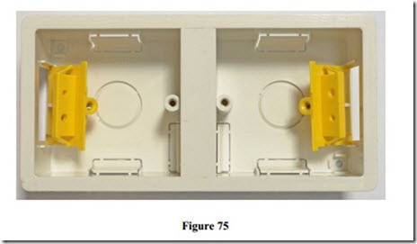
Figure 75 shows a dual dry lining box. It will allow any two single accessories to be fitted side by side. The box segregates the wiring to these accessories which is a requirement by the ETCI Rules in certain circumstances.
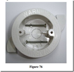
A circular dry lining box is also available which may be used to fix ceiling roses, batten lampholders, pull cord switches etc. It can be fixed to any board having a thickness between 10mm and 32mm. See Figure 76.
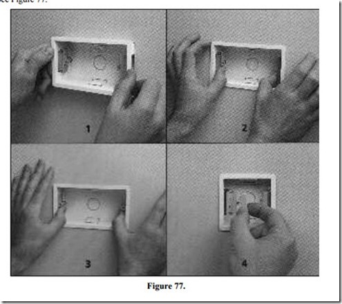
All dry lining boxes feature securing lugs which are used to retain the box in position. See Figure 77.
Fitting Dry Lining Boxes
When fitting dry lining boxes, the back of the box should be used to mark out the shape of the hole to be cut in the plasterboard. To commence cutting out this hole, pierce through the plasterboard in the centre of the marked area, using a bradawl. In the case of wooden partitions a drill bit should be used. A pad saw can then be inserted through this hole and used to neatly cut out the shape required. Alternatively a jigsaw may be used.
The box should be a snug fit in the hole. Particular care should be taken when cutting out holes for circular boxes. Circular boxes have either ribbed or shaped sections to prevent rotation in the hole.
Dry lining boxes have a large flange at the front, which prevents them passing through the hole into the cavity. This flange matches the profile of the accessory front plate.
To install an accessory using a dry lining box, proceed as follows:
· Cut a suitable hole in the plasterboard as described above.
· Install the required cables through this hole.
· Remove the required knockouts from the box.
· Pass the cables through these entries.
· Work the box into the hole in the plasterboard.
· Position the securing lugs behind the plasterboard.
· Connect the cables to the accessory.
· Position the accessory against the box flange, being careful not to damage the cables.
· Pass fixing screws through accessory and screw into the brass inserts in the securing lugs.
· Tighten the screws until the accessory is secure.
Tightening of the fixing screws pulls the securing lugs of the box against the inner surface of the dry lining board.
