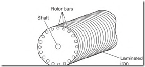
The motor’s amperes and torque are affected by various designs of the rotor bars. The type of metal used, the bar shape, and size all affect the motor’s amperes and torque (from zero to full speed).
Cast aluminum is the most common metal used in squirrel cage rotors. Aluminum makes it easier and cheaper to mass-produce rotors. However, because of the low melting temperature of aluminum, rotor bars and end rings have to be oversized to carry the high starting current. (This reduces the amount of iron that is needed for the magnetic lines of force.) The overall size of the rotor must be larger when aluminum is used instead of copper or brass.
Rotor bars made of copper (and/or other alloys) conduct high-ampere flow (that would melt aluminum). An example is the small copper rotor bars that are used in high-slip motors. Their small size gives them high resistance, which limits the amperes in the rotor winding.
Ampere flow in all motor windings is very high when a motor starts. The motor’s current demand (the instant it starts) is the same as the locked rotor current. The squirrel cage winding (with locked rotor) is similar to a shorted secondary in a transformer. (If both ends of each turn in a transformer’s secondary were welded to two separate bars of copper, the resulting ampere flow would resemble that of a locked squirrel cage rotor.) When the rotor is locked, the bar size and the resistance of the bar’s metal are all that control the current flow in its winding. (Large rotor bars have greater area for current flow than small rotor bars.) Ampere demand can be many times the motor’s nameplate value.
When the motor is at 0 RPM (locked rotor), the slip is 100 percent. (Percent of slip is synchronous speed minus the rotor speed divided by synchronous speed times 100.) At this time, the rotating magnetic field is cutting the squirrel cage winding bars at maximum hertz. As the speed of the rotor increases, slip decreases, and the rotor hertz decrease. The power supply hertz times percent of slip equals rotor hertz. Rotor hertz ranges from 0.3 to 1.5 1-IZ at full-load speed (depending on the rotor bar design). When the rotor hertz is this low, fewer lines of force cut the rotor bars, so less power
is transformed into them. Since the rotor’s power comes from the stator, the stator amperes drop to normal (at rated speed).
Phase Angle
Phase (in the term phase angle) means a winding. (The squirrel cage is the rotor’s winding.) Angle means time.
Angle, in this case, is a reference to the time that the current flows in two respective windings and creates magnetism. Phase angle is the difference (in time) between when one winding and another winding reach peak magnetic power
The phase angle has a bearing on a motor’s torque. A motor with a good phase angle (when starting) has high starting torque, but not necessarily a high ampere demand. High amperes don’t always mean high starting torque.
Small Rotor Bars
When a squirrel cage induction motor is energized, there’s an instant of locked rotor condition. At this time, magnetic lines of force of the rotating magnetic field penetrate the rotor’s iron only about 3/8 inch. A voltage is transformed into small rotor bars located within this 3/8 inch (Fig. 5.10). The ampere flow in the rotor poles (transformed amperes) and the ampere flow in the stator poles (line amperes) will peak in value at nearly the same time. When this happens, the motor has a good phase angle (near 90 0 ) between stator and rotor windings.
FIGURE 5.10 Small rotor bars, located close to the surface of the rotor, will have ampere flow that nearly matches (in time) the stator amperes.
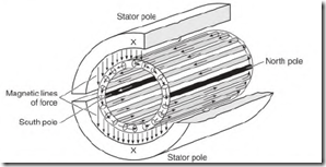
FIGURE 5.11 Poles form in the rotor’s iron as current flows in the rotor bars.
Poles form in the rotor iron because of ampere flow in the rotor bars. When peak magnetism in the rotor poles and stator poles occurs at nearly the same time, the result is very high starting torque (Fig. 5.11).
Ampere flow is restricted by the small size of the rotor bars. Power transformed into the rotor bars comes from the stator winding. (Ampere flow in the stator is normally high when starting.)
Large Rotor Bars
As with small rotor bars, the power transformed into large rotor bars comes from the stator pole’s rotating magnetic field. (Large bars can carry higher current than small bars.) The current flow forms poles in the rotor iron. Large rotor bars (because of their shape) are surrounded by a lot of iron.
Magnetizing the surrounding iron causes a delay of current flow in the bars (inductance). This delay in current flow (in the rotor bars) causes peak magnetism to occur later in the rotor poles than in the stator poles. The magnetic power of the stator poles will have peaked (and decayed to a lower value) when the magnetic field of the rotor reaches its peak power. The result is a poor phase angle.
The torque-producing magnetic interaction of the two windings is highest when both windings reach peak magnetism at nearly the same time. Low starting torque is the result of out-of-step peak magnetism, not the number of amperes in the squirrel cage winding.
Code Letter
The code letter (found on the motor’s nameplate) determines a single-phase or three-phase motor’s inrush amperes. Use the code letter and the following formulas to select the right overload protection:
Code letter value x hp x 1000 + voltage for single-phase
Code letter value x lap x 577 + voltage for three-phase (1000 x 1.73 = 577)
For 40 horsepower, 440 volts, three-phase, code F (5.3 is midrange),
5.3 x 40 x 577 + 440 = 278 inrush amperes
Three-phase motor controllers are horsepower rated. The overload protection size is selected to fit each individual motor.

