So far we did assume that all the flux per slot pitch goes radially through the teeth. Especially with heavily saturated teeth, a good part of magnetic path passes through the slot itself. Thus, the tooth is slightly “discharged” of flux. We may consider that the following are approximates:
Bt = Bti −c B b1 g s,r /bts,r; c1 <<1.0 (5.48)
= Bg bts,rbts,r+ bs,r (5.49)
Bti
The coefficient c1 is, in general, adopted from experience but it is strongly dependent on the flux density in the teeth Bti and the slotting geometry (including slot depth [2]).
5.4.3 Third harmonic flux modulation due to saturation
As only inferred above, heavy saturation in stator (rotor) teeth and/or back cores tends to flatten or peak, respectively, the airgap flux distribution.
This proposition can be demonstrated by noting that the back core flux density Bcs,r is related to airgap (implicitly teeth) flux density by the equation
Bcs,r = Cs,r Bts,r θer dθer; θer = p1θ (5.50)
relative relative fluxflux density density
B >0ts,r B <0ts,r
Figure 5.11 Tooth and core flux density distribution
a.) saturated back core (Bts,r3 > 0); b.) saturated teeth (Bts,r3 < 0)
Magnetic saturation in the teeth means flattening Bts,r(θ) curve.
Bts,r (θ =) Bts,r1 cos(θer − ω1t)+ Bts,r3 cos 3( θer − ω1t) (5.51)
Consequently, Bts,r3 > 0 means unsaturated teeth (peaked flux density, Figure 5.11a). With (5.51), equation (5.50) becomes = Cs,r Bts,r1 sin(θer − ω1t)+ Bts,r33 sin 3( θer − ω1t) (5.52)
Bcs,r
Analyzing Figure 5.11, based on (5.51) – (5.52), leads to remarks such as
Oversaturation of a domain (teeth or core) means flattened flux density in that domain (Figure 5.11b).
In paragraph 5.4.1. we have considered flattened airgap flux density–that is also flattened tooth flux density–and thus oversaturated teeth is the case treated.
The flattened flux density in the teeth (Figure 5.11b) leads to only a slightly peaked core flux density as the denominator 3 occurs in the second term of (5.52).
On the contrary, a peaked teeth flux density (Figure 5.11a) leads to a flat core density. The back core is now oversaturated.
We should also mention that the phase connection is important in third harmonic flux modulation. For sinusoidal voltage supply and delta connection, the third harmonic of flux (and its induced voltage) cannot exist, while it can for star connection. This phenomenon will also have consequences in the phase current waveforms for the two connections. Finally, the saturation produced third and other harmonics influence, notably the core loss in the machine. This aspect will be discussed in Chapter 11 dedicated to losses.
After describing some aspects of saturation – caused distribution modulation, let us present a more complete analytical nonlinear field model, which also allows for the calculation of actual spatial flux density distribution in the airgap, though with smoothed airgap.
5.4.4 The analytical iterative model (AIM)
Let us remind here that essentially only FEM [5] or extended magnetic circuit methods (EMCM) [6] are able to produce a rather fully realistic field distribution in the induction machine. However, they do so with large computation efforts and may be used for design refinements rather than for preliminary or direct optimization design algorithms.
A fast analytical iterative (nonlinear) model (AIM) [7] is introduced here for preliminary or optimization design uses.
The following assumptions are introduced: only the fundamental of m.m.f. distribution is considered; the stator and rotor currents are symmetric; – the IM cross-section is divided into five circular domains (Figure 5.12) with unique (but adjustable) magnetic permeabilities essentially distinct along radial (r) and tangential (θ) directions: µr, and µ0; the magnetic vector potential A lays along the shaft direction and thus the model is two-dimensional; furthermore, the separation of variables is performed.
Magnetic potential, A, solution
Figure 5.12 The IM cross-section divided into five domains
The Poisson equation in polar coordinates for magnetic potential A writes
J (5.53)
Separating the variables, we obtain
A(r,θ) = R(r) ⋅ T(θ) (5.54)
Now, for the domains with zero current (D1, D3, D5) – J = O, Equation (5.53) with (5.54) yields
α2
R r( ) dr dr2 ; T( )θ d T2dθ( )2θ = −λ2 (5.55) with α2 = µθ/µr and λ a constant.
Also a harmonic distribution along θ direction was assumed. From (5.55):
r2 d R r2dr2( ) + r dR rdr( ) − λ2R = 0 (5.56)
and d T2dθ( )2θ + αλ22 T = 0 (5.57)
The solutions of (5.56) and (5.57) are of the form
R r( )= C r1 λ + C r2 −λ (5.58)
T( )θ = C cos3 αλ θ + C sin4 αλ θ (5.59)
as long as r ≠ 0.
Assuming further symmetric windings and currents, the magnetic potential is an aperiodic function and thus,
A(r,0) = 0 (5.60)
π = 0 (5.61)
A r, p1
Consequently, from (5.59), (5.57) and (5.53), A(r,θ) is
A r,( θ =) (g r⋅ p1α + h r⋅ − αp1 )sin(p1θ) (5.62)
Now, if the domain contains a homogenous current density J,
J = J sin pm ( 1θ) (5.63) the particular solution Ap(r,θ) of (5.54) is:
Ap (r,θ =) Kr sin P2 ( 1θ) (5.64)
µ −µ µr pθ θ Jm (5.65) with K = − 4 2µ
r 1
Finally, the general solution of A (5.53) is
A r,( θ =) (g r⋅ p1α + h r⋅ − αp1 + Kr2 )sin p( 1θ) (5.66)
As (5.66) is valid for homogenous media, we have to homogenize the slotting domains D2 and D4, as the rotor and stator yokes (D1, D5) and the airgap (D3) are homogenous.
Homogenizing the Slotting Domains.
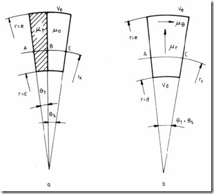
The main practical slot geometries (Figure 5.13) are defined by equivalent center angles θs, and θt, for an equivalent (defined) radius rm4, (for the stator) and rm2 (for the rotor). Assuming that the radial magnetic field H is constant along the circles rm2 and rm4, the flux linkage equivalence between the homogenized and slotting areas yields
µtHθt xr L1 +µ0Hθs xr L1 = µrH(θ +θt s ) r Lx 1 (5.67)
Consequently, the equivalent radial permeability µr, is
µ θ + µ θt t 0 s (5.68)
µ =r θ + θt s
For the tangential field, the magnetic voltage relationship (along A, B, C trajectory on Figure 5.13), is
VmAC = VmAB + VmBC (5.69)
Figure 5.13 Stator and rotor slotting With Bθ the same, we obtain Bθ (θ + θt s )rx = Bθ θtrx + Bθ θs xr (5.70)
Consequently,
µθ = µ µµ θ + µ θt 0 0t(θ + θt t ss ) (5.71)
Thus the slotting domains are homogenized to be characterized by distinct permeabilities µr, and µθ along the radial and tangential directions, respectively.
We may now summarize the magnetic potential expressions for the five domains:
A r,1( θ =) (g r1 p1 + h r1 −p1 )sin p( 1θ); a’= a < r < b
2
A r,3( θ =) (g r3 p1 + h r3 −p1 )sin p( 1θ); c < r < d
A r,5( θ =) (g r5 p1 + h r5 −p1 )sin p( 1θ); e < r < f (5.72)
A2 (r,θ =) (g r2 p1α2 + h r2 − αp1 2 + k r2 2 )sin p( 1θ); b < r < c
A4 (r,θ =) (g r4 p1α4 + h r4 − αp1 4 + k r4 2 )sin p( 1θ); d < r < e
µ µr4 θ4 Jm4
4
with KK42 = −= + 4µµr4r2µ µr2−−ppθ11222µµθθ42 Jm2 (5.73)
Jm2 represents the equivalent demagnetising rotor equivalent current density which justifies the ⊕ sign in the second equation of (5.73). From geometrical considerations, Jm2 and Jm4 are related to the reactive stator and rotor phase currents I1s and I2r′, by the expressions (for the three-phase motor),
Jm2WK1 w1I’2r
(5.74)
Jm4WK1 w1 1sI
The main pole-flux-linkage Ψm1 is obtained through the line integral of A3 around a pole contour Γ (L1, the stack length):
ψm1 =∫ A dl3 = 2L A1 3d, 2πP1 (5.75)
Γ
Notice that A3(d, π/2p1,) = −A3(d,– π/2p1,) because of symmetry. With A3 from
(5.72), ψm1 becomes
ψm1 = 2L g d1( 3 p1 + h d3 −p1 ) (5.76)
Finally, the e.m.f. E1, (RMS value) is
E1 = π 2f WK1 1 w1ψm1 (5.77)
Now from boundary conditions, the integration constants gi and hi are calculated as shown in the appendix of [7].
The computer program
To prepare the computer program, we have to specify a few very important details. First, instead of a (the shaft radius), the first domain starts at a′=a/2 to account for the shaft field for the case when the rotor laminations are placed directly on the shaft. Further, each domain is characterized by an equivalent (but adjustable) magnetic permeability. Here we define it. For the rotor and stator domains D1, and D5, the equivalent permeability would correspond to rm1 = (a+b)/2 and rm5 = (e+f)/2, and tangential flux density (and θ0 = π/4).
(
B1θ r ,m1 θ0 )= −p1g1 a +2 b p1 −1 −h1 a +2 b − −p1 1sin π4
B (r , ) e+f p1 −1 e+f − −p1 1sin π (5.78)
5θ m5 0 p1 g5 −h5 θ = −
2 2 4
For the slotting domains D2 and D4, the equivalent magnetic permeabilities correspond to the radiuses rm2 and rm4 (Figure 5.13) and the radial flux densities B2r, and B4r.
BB24rr (rm2,θ0 )= p g r1(( 2 m2pp11α −α −24 11 ++ h rh r24 mm24− α −− α −pp11 24 11 ++ K rK r24 mm24 ))cospcosp11θθ00 (5.79)
(rm4,θ0 )= p g r1 4 m4
with cosP1θ0 = 0.9 … 0.95. Now to keep track of the actual saturation level, the actual tooth flux densities B4t, and B2t, corresponding to B2r, H2r and B4r, H4r are
B2t = θt1θ+ θs2 B2r − c0 θs2 µ
B4t = θt4θ+ θt2 s4 B4r − c0 θθθt2s4t4 µ00HH24rr (5.80)
t4
The empirical coefficient c0 takes into account the tooth magnetic unloading due to the slot flux density contribution.
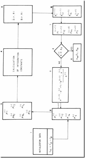
Finally, the computing algorithm is shown on Figure 5.14 and starts with initial equivalent permeabilities.
For the next cycle of computation, each permeability is changed according to
µ(i+1) = µ( )i + c1(µ(i+1) − µ( )i ) (5.81)
It has been proved that c1= 0.3 is an adequate value, for a wide power range.


