Frequency Converter
As it was discussed earlier, in order to achieve a variable speed AC motors both the fre- quency and the amplitude of the supplied voltage must be changed. The purpose of this section is not to give detailed circuit diagrams but to briefly explain the basic methods.
The idea of using a variable frequency supply to control the speed of AC motors is not new and rotating frequency converters have been employed for many years. These are used principally in multi-motor mill drives and in special applications where a high operating frequency is chosen in order to permit the use of compact AC motors. Nowadays the rotating machine variable frequency AC power genera- tions are being largely supplanted by static conversion methods.
The performance and reliability of variable speed AC systems is improved if the rotating frequency converter is replaced by static methods of variable frequency power generation. The renewed interest in static frequency conversion is due to the improved characteristics of the thyristor and transistors as compared with other switching devices. The thyristor is a more efficient switching since the voltage drop in the on condition is only about one volt.
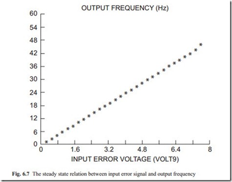
In steady state the motor frequency (rad/sec) for most frequency inverter is proportional to the error voltage. Although the frequency of motor changes when the error signal is received, there is dynamical behavior that should be considered. In most frequency converter, the relation between the motor speed and apply voltage and input error signal may be shown to be the same as the case discussed for DC motors. An equation similar to Eqs. (6.6) and (6.7).
Figure 6.7 shows the steady state relation between the input error signal and the output frequency of the motor. The change to the output voltage as the error signal changes is not shown. The variation of output voltage as error changes are different for various frequency converters but basically as the output frequency reduces the voltage to the motor must also change the same proportion as the frequency changes.
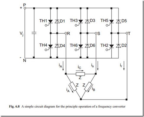
Figure 6.8 shows the basic operation of the frequency inverters. First the three phase power supply is converted to pure DC. Then thyristors are used to generate variable frequency input to the motor.
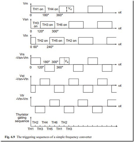
The electronics must change frequency of the voltage connected to the motor. This is achieved by controlling the triggering period of various thyristors. The trig- gering sequence for the above mentioned circuit diagram is shown in Fig. 6.9. It shows that with electronic circuitry the thyristor must be triggered to conduct the DC power supply for a predefined period. It must be stressed that when thyristors are turned on they will continue to conduct until the current becomes zero. There- fore, in all frequency converters, an electronic circuitry must be designed to force them to stop conducting at a predefined time.
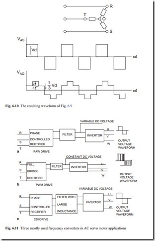
Figure 6.10 shows a typical resulting wave form. It is not a pure sine wave. The motor will respond to the fundamental frequency of the output wave form. The higher harmonics which basically are at higher frequency generate a lot of noise in the motor especially at low frequency.
The most available frequency converters are of three types with acceptable dynamic performance for position control applications. In the pulse amplitude modulated converter (PAM), the amplitude of output voltage is controlled at the rectifier stage with the aid of phase controlled rectifiers (thyristors) and the frequency is controlled at the output stage (Fig. 6.11a). This achieves a constant voltage–to– frequency ratio at high frequency and the volts: Hz ratio is usually boosted at low frequencies by limiting the minimum output voltage. The main drawback is that the output voltage wave form generates harmonics components resulting in vibration and excessive noise.
The problem of vibration and noise associated with PAM drive is solved in the pulse-width modulated converter (PWM), where both the average output voltage and frequency are controlled at the output stage after the AC supply has been rectified to a constant DC source (Fig. 6.11b). This is further improved if sinusoidal pulse width modulations are used.
In the Current Source Inverter (CSI), a large inductance in the DC link produces a constant current (Fig. 6.11c), which is switched through the phases of motor coils in turn by a series of thyristors. The diodes in all types of converters effectively provide the commutations function and ensure continuity in current when thyristors are switched off. The main advantage of CSI is that large inductance in the circuit protects the electronics from any sudden current surge that could occur under faulty
conditions. The system suffers from non-sinusoidal output current waveform and the problems associated with harmonics.
Among the three types of converters described, the PWM usually gives smooth control of speed from zero to maximum with satisfactory low frequency torque capability. In all converters, a time delay between output voltage and input control signal protects the electronics and the motor from overload and sharp current surges. There must be also current limiter in the circuit to protect the windings of the motor. Therefore, the output voltage and frequency are related to the input signal approximately by a first-order transfer function in the form of
The time constant ( τ) is usually given by the manufacturer of frequency converter. The time constant may vary from a few milliseconds to 10–30 s depending on the rated power of the motor and frequency converter. The gain (a1) changes with fre- quency because of the nonlinear characteristics of output voltage and the error sig- nal ( e) which is more pronounced at low frequency.
The Eqs. (6.8) and (6.9) describe the dynamic behavior of frequency converter. However, to model the complete system, that is, the converter, motor, and load, the voltage equation of (6.8) and the operating point of the constant, must be used; and Eq. (6.7) must be used to model the dynamic behavior of the model. The frequency changes are inherent in the system and will be accounted for implicitly. The dy- namic behavior of other part of the system is similar to DC servo motors.
6.5 Conclusion
In this chapter, the properties of AC induction motors and various frequency con- verters were studied. The main object was to describe the principle behavior when AC induction motors are used as servo motors. They are very reliable because there is no brush. The three phase motors are considered because their speed changes with frequency and this is the best method of changing speed.
There are various research centers that are studying how to improve the dynamic behavior of AC servo motors especially at low frequency. The reader is encouraged to obtain a catalogue of a typical AC motor and a catalogue of a matching frequency converter and to model the complete system. This is a good exercise to study the dy- namic behavior of AC servo motors in speed or position control. It should be noted that AC motors are available at various speed ratings and the reader should study the benefits of using gearboxes to reduce the speed. The procedure is similar to that described for DC servo motors.


