The Bubbler System
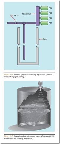
Another method often used to sense liquid level is the bubbler system. This method does not employ the use of float switches. The liquid level is sensed by pressure switches (Figure 9 – 6). A great advantage of this sys- tem is that the pressure switches are located outside the tank, which makes it unnecessary to open the tank to service the system.
The bubbler system is connected to an air line, which is teed to a manifold and to another line that extends down into the tank. A hand valve is used to ad- just the maximum air flow. The bubbler system operates on the principle that as the liquid level in- creases in the tank, it requires more air pressure to blow air through the line in the tank. For example, a 1-square-inch column of water 26.7 inches in height weighs 1 pound. Now assume a pipe with an inside area of 1 square inch is 10 feet in length. It would require a pressure of 4.494 psi to blow air through the pipe.
If the water level was 7 feet in height it would require a pressure of only 3.146 psi.
Since the pressure required to bubble air through the pipe is directly proportional to the height of the liquid, the pressure switches provide an accurate mea- sure of the liquid level. The pressure switches shown in Figure 9 – 6 could be used to control the two pump
Figure 9 – 4 Float level is set by the length of the conductor.
(Source: Delmar/Cengage Learning.)
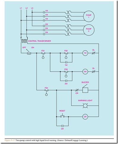
circuit is shown in Figure 9 – 5. Float switch FS1 detects the lowest point of liquid level in the tank and is used to turn both pump motors off. Float switch FS2 starts the first pump when the liquid level reaches that height. If pump #1 is unable to control the level of the tank, float switch FS3 will start pump motor #2 if the liquid level should rise to that height. Float switch FS4 operates a warning light and buzzer to warn that the tank is about to overflow. A reset button can be used to turn off the buzzer, but the warning light will remain circuit previously discussed by replacing the float switches with pressure switches in the circuit shown in Figure 9 – 5.
Microwave Level Gauge
The microwave level gauge operates by emitting a high frequency signal of approximately 24 gigahertz into a tank and then measuring the frequency difference of the return signal that bounces off the product (Figure 9 – 7). A great advantage of the microwave level gauge is that no mechanical object touches or is inserted into the product. The gauge is ideal for measuring the level of turbulent, aerated, solids-laden, viscous,
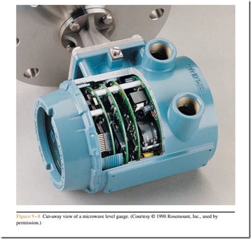
corrosive fluids. It also works well with pastes and slurries. A cut-away view of a microwave level gauge is shown in Figure 9 – 8.
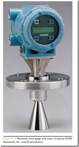
The gauge shown in Figure 9 – 9 has a primary 4 to 20 milliampere analog signal. The gauge can accept one RTD (Resistance Temperature Detector) input signal. The gauge can be configured to display the level, calculated volume, or standard volume. A microwave level gauge with meter is shown in Figure 9 – 9.
Review Questions
1. Describe the sequence of operations required to
(a) pump sumps and (b) fill tanks.
2. Draw the normally open and normally closed contact symbols for a float switch.
3. What type of float switch does not have a differential setting?
4. What is the advantage of the bubble type system for sensing liquid level?
5. Assume a pipe has an inside diameter of 1 square inch. How much air pressure would be required to bubble air though 25 feet of water?


