Flow Switches
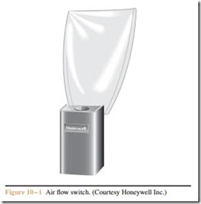
Flow switches are used to detect the movement of air or liquid through a duct or pipe. Air flow switches are of- ten called sail switches because the sensor mechanism resembles a sail (Figure 10 – 1). The air flow switch is constructed from a snap-action micro switch. A metal arm is attached to the micro switch. A piece of thin metal or plastic is connected to the metal arm. The thin piece of metal or plastic has a large surface area and of- fers resistance to the flow of air. When a large amount of air flow passes across the sail, enough force is produced to cause the metal arm to operate the contacts of the switch.
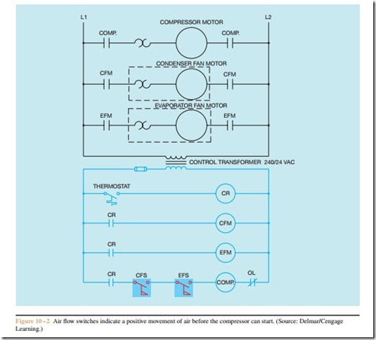
Air flow switches are often used in air conditioning and refrigeration circuits to give a positive indication that the evaporator or condenser fan is operating before the compressor is permitted to start. A circuit of this Figure 10 – 1 Air flow switch. (Courtesy Honeywell Inc.)
type is shown in Figure 10 – 2. When the thermostat contact closes, control relay CR energizes and closes all CR contacts. This energizes both the condenser fan motor relay (CFM) and the evaporator fan motor relay (EFM). The compressor relay (Comp.) cannot start be- cause of the two normally open air flow switches. If both the condenser fan and evaporator fan start, air movement will cause both air flow switches to close and complete a circuit to the compressor relay.
Notice in this circuit that a normally closed over- load contact is shown in series with the compressor contactor only. Also notice that a dashed line has been drawn around the condenser fan motor and overload symbol, and around the evaporator fan motor and over- load symbol. This indicates that the overload for these motors is located on the motor itself and is not part of the control circuit.
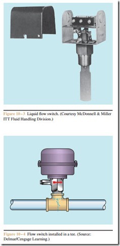
Liquid flow switches are equipped with a paddle that inserts into the pipe (Figure 10 – 3). A flow switch can be installed by placing a tee in the line as shown in Figure 10 – 4. When liquid moves through the line, force is exerted against the paddle, causing the contacts to change position.
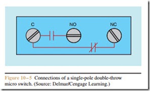
Regardless of the type of flow switch used, they generally contain a single-pole double-throw micro switch (Figure 10 – 5). Flow switches are used to control
power can be supplied to the rest of the control circuit. When the pressure switch contact closes, power is supplied to the lube oil pump relay. The flow switch detects the flow of lubricating oil before the compressor is permitted to start. Note that a red warning light indicates when there is no flow of oil. To connect the flow switch in this circuit, power from the control relay contact must be connected to the common terminal of the flow switch so that power can be supplied to both the normally open and normally closed contacts (Figure 10 – 7). The normally open section of the switch connects to the coil of the compressor contactor, and the normally closed section connects to the red pilot light.
Regardless of whether a flow switch is intended to detect the movement of air or liquid, the NEMA symbol is the same. Standard NEMA symbols for flow switches are shown in Figure 10 – 8.
low current loads such as contactor or relay coils or pilot lights. A circuit that employs both the normally open and normally closed contact of a flow switch is shown in Figure 10 – 6. The circuit is designed to control the operation of an air compressor. A pressure switch controls the operation of the compressor. In this circuit, a normally open push button is used as a reset button. The control relay must be energized before


