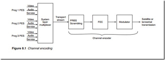
Channel encoding
The transport stream emerging from the system layer multiplexer forms what is known as a channel. It is also known as a multiplex carrying a num- ber of different programmes. Before transmission can take place, the packe- tised transport stream is first scrambled to obtain an even distribution energy across the channel. This is followed by forward error correction (FEC) before the signal is finally modulated and transmitted (Figure 8.1). The channel encoder is agnostic as the type of encoding (MPEG-2, MPEG-4, AVC, ACC, etc.). The delivery of audio and video encoded data is the same regardless of the encoding tools used.
Scrambling
Scrambling is the process of rearranging the order of the data bits. It is not to be confused with encryption, which is the replacement of the original information by an alternative code pattern. Encryption is a secure system and it is used in conditional access applications where restrictions apply. Scrambling is used only for energy dispersal. The problem with plain unscrambled bitstreams is that they are likely to have long series of zeros and ones, which introduce a d.c. component. This results in an uneven distribution of energy making the transmission highly inefficient. If the bit- stream can be randomised and the series of 0s and 1s scattered, a more even energy distribution will be obtained. This is the purpose of scrambling. Totally random scattering is not possible as there is no way of descrambling the bits back to their original order at the receiver. However, a pseudo- random scattering with a known pattern can be easily descrambled at the receiving end to regenerate the original order of the data bits. To ensure the start of each transport packet can be recognised, the start byte is not scram- bled and the scrambler is disabled for the duration of the start code.
Forward error correction
Digital signals, especially signals with a high level of data compression, require an efficient error protection capability. In digital video broadcast- ing (DVB), the bit error rate (BER) must be better than 10-11 or 1 in 100,000 million bits. This is equivalent to less than 1 uncorrected bit in 1 h of transmission. A transmission channel with such a low BER is known as a quasi-error-free (QEF) channel. DVD re-production and cable television are such channels. However, open communication, terrestrial or satellite,
are prone to errors caused by a variety of reasons including weather conditions and reflections. To ensure such communication media meet the QEF specification, preventive measures must be taken to ensure that errors introduced by the transmission medium are detected and, where possible, corrected. This is the function of the FEC block.
In general, if an error is detected at the receiving end of a communica- tion system, it can be corrected in two different ways: the recipient can request the original transmitter for a repeat of the transmission, or the recipient can attempt to correct the errors without any further information from the transmitter. Whenever it is a realistic option, communication sys- tems tend to go for retransmission. But if the distances are large, perhaps to contact a space probe, or if real-time signals are involved, such as in audio and video broadcasting, then retransmission is not an option. These cases require error correction techniques.
Error correction is common place in all walks of life including aural communication. It makes use of redundancy in messages. Redundancy exists naturally in all codes including languages. In ordinary English, the u following a q is quite unnecessary and ‘at this moment in time’ can be shortened to ‘at this moment’ or even ‘now’. Redundant letters or words play a very important role in communication. They allow the recipient to make sense of distorted information. This is how we can make sense of badly spelled emails, a text message, a badly tuned receiver, and so on.
In digital communications, redundancy means unnecessary data that occupies precious bandwidth and the purpose of data compressions is precisely to remove them. But without redundancy, there cannot be error correction. For this reason, controlled redundancy bits are added to enable data corrupted in transmission to be corrected at the receiving end.
The most basic technique, parity, provides rudimentary error detection. It involves a single parity bit at the end of a digital word to indicate whether the number of 1s is even or odd (Figure 8.2). There are two types of parity checking. Even parity (Figure 8.2a) is when the complete coded data, including the parity bit, contains an even number of 1s. Odd parity (Figure 8.2b) is when the complete coded data contains an odd number of 1s. At the receiving end, the number of 1s is counted and checked against the parity bit; a difference indicates an error. This simple parity check can only detect an error occurring in a single bit. An error affecting two bits will go undetected. Furthermore, there is no provision for determining which bit is actually faulty. For these reasons, more sophisticated tech- niques are normally used with higher levels of redundancy. One such technique is FEC employed in digital television (DTV) broadcasting.
