DQPSK decoder
The phase demodulator or detector works on the same principles as an FM detector in which a variation in phase (or frequency) produces a variation in the d.c. output. In the case of two-phase modulation, the d.c. out- put of the detector has two distinct values, representing logic 1 and logic
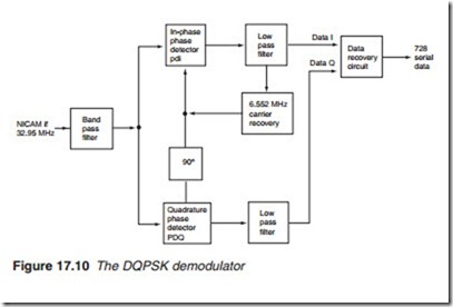
0. However, in the case of quadrature, i.e. four-phase modulation, the out- put of the detector is ambiguous. The same output is obtained for a 90° and 270° phase shifts. Similarly for phase shifts of 0° and 180°. In order to resolve the ambiguities, a second phase detector operating in quadrature (90°) is used. Figure 17.10 shows the main elements of a DQPSK demodulator using an in-phase phase detector (PDI) and a quadrature phase
detector (PDQ). The outputs from the two-phase detectors, data I and Q, are fed into a data recovery circuit which reproduces the original 728-bit serial data stream. The 6.552 MHz reference carrier frequency is generated by a carrier recovery circuit which includes a crystal-tuned voltage- controlled oscillator (VCO) and a phase-locked loop (PLL).
The data recovery circuit includes a second PLL locked to the bit rate of 728 kHz. In order to ensure a ‘clean’ bit rate clock, a master system clock which is a multiple of the bit rate is used. In this case, a clock frequency of 728 X 8 = 5824 kHz = 5.824 MHz is used. The bit rate is then retrieved by dividing the master system clock by eight. The I and Q data streams from the DQPSK detector are fed into a differential logic decoder, which pro- duces the corresponding 2-bit parallel data. The pairs of parallel data are then fed into a parallel-to-serial converter, which reconstructs the original 728-bit serial stream before going to the NICAM decoder.
