VIDEO HEAD DRUM
The heart of a videorecorder is its head-drum assembly. The lower (stationary) section contains one half of the rotary transformer in most designs; and consists of a monobloc cast-and-machined assembly whose most critical features are its peripheral surface fin- ish and the angle and finish of the guide rabbet. For all formats the whole upper section of the drum rotates, carrying the heads and the second half of the rotary transformer. The heads themselves consist of tiny chips of ferrite in ‘ring’ form, around which is wound a dozen
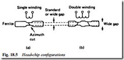
or so turns of very fine enamelled wire. The protruding section of each head chip is precision-ground to the required dimensions, after which the gap is cut across the face – at an angle dictated by the azimuth requirements. The effective ‘width’ of the head and the magnetic track it writes is determined by the length of the magnetic gap in fact, and by grinding indentations in the chip at each end of the gap, ‘head-width’ is precisely defined as shown in Fig. 18.5; some heads have double gaps (with separate windings for each), often with opposing azimuth angles and different widths, all achieved by micro- grinding of the gap and head face. An idea of the construction of such a head is given in Fig. 18.5. The heads are fixed to brass mount- ing tabs which in turn are screwed to the lip of the head drum. The positioning of the heads is very critical indeed; it is set up in the fac- tory using precision optical equipment whose resolution is better than one micron. Fig. 17.4 shows detail of the head construction. To accommodate the gradient which the tape must climb on its way around the head drum (the tape tracks are written at an angle of about 5° to the ribbon edge) the whole drum assembly is mounted at scanning angle so that the tape can remain parallel to the deck surface throughout its passage.
All head drums spin anticlockwise in domestic formats, and the tape passes anticlockwise around the drum, except in review-replay (backward search) mode. In all cases the head enters onto the tape at its lower edge to read or write its slant track, leaving the tape at its top edge, as shown in the diagrams in Chapter 13.
Head service
The most expensive and vulnerable component on the deck is the video head-drum assembly. As a general rule it is also the one most vulnerable to wear – 2000 operating hours is an oft-quoted life expectation. As the head-tips wear, their penetration ability decreases
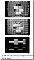
to the point where replayed pictures from known-good tapes are intolerably marred by dropouts, as depicted in the photo of Fig. 18.6(a). A common effect of head wear is the streaking and transient- distortion pictured in Fig. 18.6(b). The effects shown can easily be caused by defects in the replay amplifiers, so after head cleaning (see later) the heads themselves should not be condemned before the replay circuits have been checked with regard to: (a) correct opera- tion of DOC; (b) condition and operating point of preamplifiers, demodulator and limiter circuit. Very often the noise, streaking or other effect will have a heavy flicker component at 25 Hz rate, a sure indication that the trouble stems from one of the two head channels. Examination of the replay video f.m. envelope at a point after the head-switch but before the limiting stage (a suitable test point is given in the manufacturer’s service manual) will reveal a large difference in output levels between the heads as shown in the oscillogram of Fig. 18.6(c) which is taken from an oscilloscope whose timebase is trig- gered from the head PG or flip-flop waveform, shown below. The performance of the suspect head in record mode (replay its tape in a known-good machine to check) is a useful clue as to whether it is faulty.
Sometimes the first indication of the onset of head wear is excessive dropout during replay of ‘self-made’ recordings – the double pas- sage of the video f.m. signal through the substandard head(s) emphasises the problem, which at this stage may not be apparent during replay of well-recorded (i.e. library or alignment) tapes. With experience the state of wear of the video head tips can be judged by their ‘feel’ to a fingertip through a thin layer of cleaning material; a close examination of the ferrite tips (even with a powerful magnify- ing glass) is unlikely to reveal the state of wear that may be present, but will reveal any physical damage, e.g. chipped or cracked face.
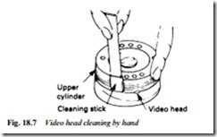
The symptoms shown in Fig. 18.6 will often be due to a build-up of tape oxide and other debris on the head tips, forming a barrier between head and tape; in severe cases no picture at all can be recorded or replayed. Cleaning of the heads is best done by hand rather than a cleaning tape. Various solvents can be used, including the specially prepared types offered for sale by videorecorder manufacturers and component distributors; surgical spirit is an adequate alternative. Using a lint-free cloth (or, better, a fine chamois or buckskin surface) well moistened with solvent, rub each video head sideways, that is in the direction of tape travel. Gentle-to-moderate pressure should be used, and great care taken not to move the head chip vertically, which will break the adhesive by which the head is held in place on its brass mounting tab. Fig. 18.7 shows how the head
is held steady with one hand while being cleaned with the other – here a special cleaning stick is being used.
It is possible to clean the head chips by holding the cleaner still on the peripheral surface of the drum then rotating the latter by direct or indirect means. Whenever this is done, however, it is essential that the head is turned anticlockwise or the ferrite chips may be dam- aged. Sometimes a head will continue to display wear/‘blocked’ symptoms after a thorough ‘wet’ clean; before condemning it (and since at this point there is nothing to lose) it is worth trying the effect of bearing moderately hard on the front surface of the head with a stiff card (like a business or visiting card) while rotating the drum anticlockwise by hand. Sometimes this will restore normal operation. Cases where heads ‘block’ and need cleaning at regular intervals may occasionally be due to faulty (rough-surfaced) head chips, but are more often attributable to the use of one or more tapes which are shedding oxide excessively, perhaps as a result of a roughened or torn surface sustained in an earlier ‘tape-chewing’ incident in a faulty deck.
When head cleaning fails to cure the symptom, and electrical tests exonerate the drive and preamp circuits, the head disc must be replaced. It is important to ensure that the new head is fitted and wired correctly according to the colour code of individual head leads, since a head fitted 180° ‘out of phase’ will cause puzzling symptoms like no colour. Provided that no dirt particles enter under the head during replacement, and that the securing screws are equally tight, correct running level of the heads is assured by the factory-sealed settings. For some machines the exact centring of the head disc on its mounting platform must be checked and corrected by a dial- gauge with which eccentricity can be reduced to less than 2 microns;
any greater error may cause fluctuating tape tension and flutter on sound. Whether or not a dial-gauge is used, great care is necessary to avoid damage to the delicate head tips during handling and installation.
At the time of head replacement, the entire tape path should be cleaned (description follows) and the following setting points checked and adjusted as necessary: control-track head positioning; record writing current; preamplifier alignment; and record and replay head- switching points. Sometimes guide alignment may be necessary, and this, too, will be described later in this chapter. Never use an align- ment tape in a newly repaired deck in case it gets damaged: check first with a less valuable tape.


