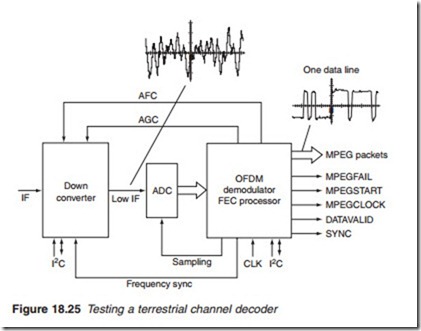
Testing channel decoder
The modulated carrier entering the channel decoder is in the form of two quadrature carriers: I and Q in the case of satellite transmission and COFDM carriers in the case of terrestrial transmission. The function of the channel decoder is to digitise the incoming carriers into a multi- bit parallel stream, demodulate them and reproduce error-free MPEG packets.
Testing a satellite channel decoder (Figure 18.24) should start with checking the dual-ADC sampling clock (if a viable test point is avail- able), which would be in the region of 55 MHz (twice a symbol rate of Mega symbols per second). The sampling clock should be present regardless of whether the tuner is locked to a channel. A wrong or miss- ing sampling clock would cause a complete malfunction of the channel decoder.
Testing the terrestrial channel decoder should follow a similar pattern to testing a satellite channel decoder. The sampling clock of the ADC if available should be checked first. It is normal to have an 18 MHz clock pulse with amplitude of around 4 V. Further checks involve testing the MPEG packets at the output of the FEC processor chip, at the output of the OFDM demodulator and at the output of the ADC. All data lines should indicate digital activities on a logic probe or an oscilloscope. Typical wave- forms are illustrated in Figure 18.25.
Testing the transport/MPEG decoder
Figure 18.26 shows a chip set for an HD decoder box comprising of a transport processor and a multi-standard MPEG decoder.
The input to the transport demultiplexer is MPEG-2 or MPEG-4 data packets together with control signals MPEGSTART, MPEGFAIL and MPEG clock from the channel decoder. The function of the demux is to reassemble the video and audio packets of the selected TV programme. Testing the demux involves checking the control signals from the channel decoder followed by the clocks. There are two types of clocks to be tested: the 27 MHz system clock and the chip clock. Each processing chip has its own chip clock (in the region of 50–90 MHz) which is invariably internally generated and must be accurate within 10% or less. The presence of a clock pulse may be tested by a logic probe. However, if the frequency has to be measured, an oscilloscope or a frequency meter must be used. An inaccu- rate clock frequency would cause total failure of the processor chip.
Testing the multi-standard MPEG decoder involves examining the input and output data streams using a logic probe to check for digital activity, or an oscilloscope to display real-time waveforms. The audio out- put is in the form of a serial L/R multiplexed PCM digital stream. The multiplexing order is determined by an L/R control signal having a fre- quency equal to half the sampling rate. The 27 MHz system clock and the decoder processing clock should be checked next, followed by the control
signals which regulate the transfer of data between the demux and the decoder.
Both the demux and the MPEG decoder have their own dedicated SDRAM memory chips for transport packet storage and video/audio stor- age, respectively. In many applications, Flash (for start-up and program- ming routines) and NVRAM (for individual settings) memory chips are also used. Memory chips may be tested by checking for digital activity along their data and address lines as well as the read or output enable (OE), write enable (WE) and chip enable (CE) control lines.

