Line output transformer
Although the scan coils are not normally transformer-coupled, a trans- former known as the LOPT (line output transformer), pronounced ‘loptie’ is employed to provide a number of functions including the e.h.t., the
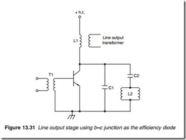
auxiliary d.c. supplies, the boost voltage, the gating pulses for a.g.c. and the reference pulse for the flywheel discriminator (Figure 13.31). In choosing the value of the tuning capacitor for the line output stage, the inductance introduced by the LOPT must be taken into account.
One important function of the LOPT is to provide the high d.c. supply voltage of 30–90 V required by the video, line and field output ampli- fiers. For receivers operating from the mains supply, this d.c. voltage may be obtained by rectifying the mains voltage. However, this is not possible for battery-operated receivers, so a boost voltage from the LOPT is used.
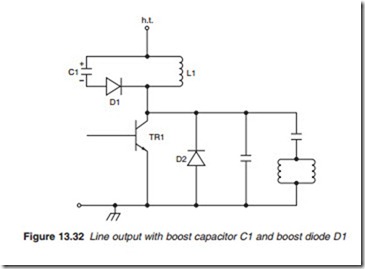
The boost voltage is obtained by the use of an efficiency diode and a storage capacitor. Consider the circuit in Figure 13.32, in which L1 is the primary winding of the LOPT, D1 is the boost diode, C1 is the storage or boost capacitor and TR1 is the line output transistor. D1 is connected in such a way that it only allows charging current to flow through C1 and prevents the discharging current from flowing through L1, thus maintain- ing the charge across C1. When TR1 is switched on, D1 conducts; this places C1 across L1. Ringing occurs and electromagnetic energy in L1 is transferred to C1, which charges up to h.t. When C1 attempts to discharge through L1, the current reverses and D1 stops conducting. Provided C1 is large, in the region of 200 j.LF, it will retain the charge across it. When TR1 is switched off to start the flyback, D1 remains off. At the end of the fly- back, TR1 collector goes negative due to the reversal of the rate of change of current in the scan coils. D1 and D2 conduct. Energy in L1 is transferred
to C1 to replace any loss in its charge. Excess energy is fedback into the h.t. supply line. C1 thus remains charged up to h.t.
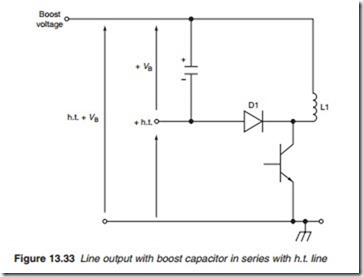
It is possible to connect the boost capacitor in series with the h.t. line to produce a boosted voltage (Figure 13.33). The voltage VB across the capac- itor, which could exceed the h.t. potential, is added to the h.t. line.


