Complete tuner
The various tuned circuits in the tuner unit must keep in step with each other as different frequencies are selected, and this calls for good matching in manufacture. The variable tuning is carried out by means of fixed Lecher bars in conjunction with varicap diodes. Tuning control, then, is carried out by varying the d.c. potential applied to the varicap diode. A swing of 30 V would scan the whole UHF television band. The tuning voltage source may be as simple as a single potentiometer or as complex as a frequency-synthesis, self-seeking ensemble. A self-seeking system, when initiated, sweeps up the TV transmission band(s) by itself, stopping each time it encounters a station for storing (manually or automatically) to a non-volatile memory, NVRAM. Frequency-synthesis offers a self-seek and memory facility along with a ‘direct addressing’ feature in which a required channel number (21–68 for UHF) can be requested by the viewer and automatically tuned. This involves a very stable crystal oscillator in a phase-locked loop (PLL) embracing the tuner’s local oscillator.
The phase-locked loop
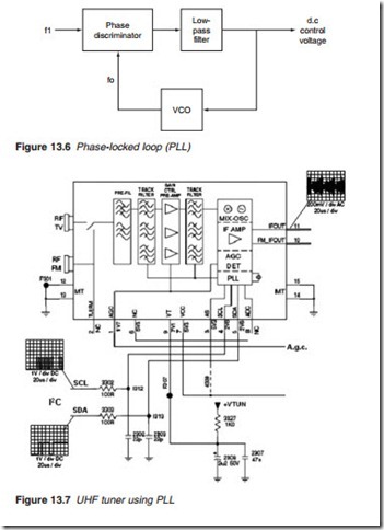
The PLL is commonly used in TV receivers to ensure stability of the IF out- put without the use of an a.f.c. Available in integrated circuit packages, the PLL is today widely used in a variety of electronic applications, including chrominance decoding. The principle of operation of the PLL is illustrated in Figure 13.6. It consists of a phase discriminator or detector, low-pass loop filter and a voltage-controlled oscillator (VCO). Without an input signal to the phase discriminator, the VCO is free running at its own natural fre- quency, fo. When a signal arrives, the phase discriminator compares the input frequency f1 with that generated by the VCO. A difference results in a d.c. output which after filtering is fed back into the VCO to change its frequency. The process continues until the two frequencies are equal and the PLL is said to be locked.
provides a facility for FM radio reception. TV IF output is provided at pin 11 and the FM IF output is available at pin 10. The a.g.c. is fed into pin 1 and tuning is controlled by an I2C serial bus (SCL and SDA) from the microcontroller. For detailed information on I2C bus operation, refer to Appendix 2.
