MAC ENCODING
The signal parameters, bandwidths and colour-encoding systems discussed in the previous chapter, and adopted for most satellite transmissions in the late 1980s, were developed in the fifties and six- ties specifically for use with terrestrial transmissions and in bands and channels already in use for a.m. TV broadcasting. In those times the overriding requirement was to achieve compatibility and reverse- compatibility with black and white transmissions. Most of the constraints within which the NTSC committee, Henri de France (SECAM) and Walter Bruch (PAL) had to work have disappeared with the virtual demise of monochrome receivers and the advent of transmission media like spacecraft and fibre-optic cables. Developments in technology have been many and great in the intervening decades, and as TV screens get bigger and viewers more discerning, the shortcomings of existing systems have come sharply to the fore. Chief amongst them are cross-colour, in which spurious blue/yellow and red/green herringbone patterns appear superimposed on fine picture details; cross-luminance, where sharp transitions in the chrominance image are accompanied on screen by a moving
luminance dot-pattern; and a shortfall of definition in both luminance and chrominance components of the picture due to the need for response filtering in both channels to avoid excessive mutual interference.
Several new analogue encoding systems have been devised for picture transmission and recording, and where they are for exclusive or closed-circuit use there is freedom to tailor the system to suit the transmission or storage medium and the signal parameters in use. Where a broadcast system is involved, however, the requirements are very stringent: the receiving and decoding equipment must be cheap, non-critical and capable of good performance; the system must preferably be capable of evolution and upgrading without losing compatibility; it must take full account of current and future technology since it will be very long lived once entrenched in domestic receiver hardware; and the performance of the system must be the best possible within the constraints of currently available channel bandwidth, transmission and reception systems and picture-display techniques. The MAC (Multiplexed Analogue Components) system fulfils these requirements, and combines a digital sound system with an f.m. analogue picture transmission. These factors permit fault- free reception at much lower signal levels: whereas about 40 dB S/N ratio is required for good reception of a.m. TV transmissions, a C/N ratio of less than 12 dB suffices for MAC broadcasts from satellites and along cables.
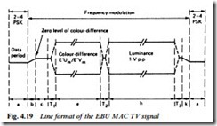
The composition of a MAC signal is shown in Fig. 4.19. Its main difference from conventional (real-time) encoding and transmission systems is its use of time-compression, calling for memory banks at both ends of the signal link for short-term storage of audio, chrominance and luminance signals. In conveying a CCIR 625-line 50 field
colour signal the overall time taken for one TV line must be 64 μs, but here this period is divided into four distinct time slots as Fig.
4.19 shows: a data period containing digital information on sound, teletext, identification and synchronisation; a clamping period at zero level for system stabilisation; a frequency-modulated chrominance signal conveying U and V information on alternate lines; and a long period of luminance information, also frequency modulated. The luminance signal is time-compressed in the ratio 3:2, and the chrominance signal in the ratio 3:1. Digital data is conveyed by PSK (Phase Shift Keying) in which logic 1 corresponds to a phase change of +90°, and logic 0 to a phase change of −90°.
The principle of PSK is fully explained in Chapter 9. The sequence of the MAC line in Fig. 4.19 in detail is as follows:
(a) 206 bits for synchronisation, sound and data, made up of 1 run-in bit, 6 bits of line sync word, 198 bits of data (in two subframes of 99 bits each) and 1 spare bit.
(b) 4 clock periods as transition from end of data, including the leading edge of a pedestal added to the signal to provide energy dispersal.
(c) 15 clock periods at 500 mV for clamping purposes.
(d) T1 10 clock periods, to include a weighted transition to colour- difference signal of 5 clock periods.
(e) 349 clock periods for f.m. colour-difference component, either U or V.
(f) T2 5 clock periods for weighted transition between colour- difference and luminance signal.
(g) 697 clock periods for f.m. luminance component.
(h) T3 6 clock periods for weighted transition from luminance signal.
(i) 4 clock periods for transition into data; includes trailing edge energy-dispersal pedestal signal.
MAC decoding
The MAC signal leaves the satellite transmitter as an f.m. carrier with a frequency around 12 GHz and a bandwidth of 27 MHz. At the receiver the digital data is gated to a PSK demodulator and thence to a decoder which produces sound, data, sync, text, conditional access and control information. The chrominance and luminance components are gated to line-stores, to be read out at normal scanning rates and recombined as part of the decoding process.

