Digital recording and camcorder
Digital recording may be carried out using a magnetic tape, an optical disk (CD or DVD) or a hard disk. In all cases, the analogue video and audio are sampled and compressed to form digital data bitstreams that are stored on the recording medium. Recording on optical discs was fully explained in Chapter 20. We shall therefore start with digital magnetic tape recording.
Digital video recording on a magnetic tape was launched in 1994 under the name of DV employing a tape cassette known as digital video cassette (DVC) and its smaller form factor MiniDV. The DV specification defines both the type of compression and the tape-recording format. Though DV quickly became the standard for home and semi-professional recording, it spawned a number of variants, most notably Sony’s DVCAM and Panasonic DVCPRO formats targeted at the professional end of the mar- ket. Sony’s consumer Digital8 format is another variant, which is similar to DV but recorded on Hi8 tape. A high-definition version of DV has also been developed under the name of HDV. While it uses the DV and MiniDV tape form factor, it employs the full MPEG-2 compression toolkit including inter-frame compression which is not used in the standard def- inition DV format.
Other formats have also been introduced including the S-VHS and the D- VHS but they did not get general acceptance by the public, especially as DVD recording started to gather pace. S-VHS improves VHS’s luminance resolution by boosting the frequency deviation of the luminance carrier. D-VHS (D for Data) is a digital video format developed by JVC, in collaboration with Hitachi, Matsushita and Philips. The main departure from S-VHS D-VHS is that D-VHS records the packetised MPEG-2 transport stream packets, the same data format used for digital television applications.
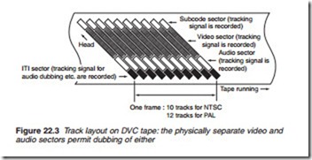
The advantages of a digital video recording system are several. The for- mat itself affords higher picture resolution, better in practice than a colour TV broadcast. The digital signal can be transferred to another (digital) tape without any loss of quality, and edited and manipulated likewise, wholly in the digital realm. Both video and audio signals can be ‘dubbed’ because they occupy different areas on the tape. The colour-bleed and -smear which arises from low chroma bandwidth in analogue tape systems dis- appears, as do the Y/C band-sharing artefacts due to PAL and other colour-encoding systems. Because the picture is built up ‘from scratch’ as it were, in the playback electronic system, there is no potential for noise or interference on picture or sound, though of course when the digital bitstream from the tape gets too corrupt the sound disappears and the pic- ture becomes progressively ‘blocky’; intermittently ‘frozen’ wholly or in segments; and then disappears altogether, just like the ‘digital cliff’ phe- nomenon in digital television broadcasting.
Digital video (DV) uses two types of cassettes: the L-size (120 X90 X 12 mm) and S-size (65 X 48 X 12 mm) known as MiniDV. Both are much smaller than an audio or Video-8 type. These are capable of storing 11 GB of data equivalent to 1 h of high-quality sound and vision in SP mode, or 1.5 h in LP mode on 6.35-mm-wide tape, with excellent sound quality and 500- line picture definition, a good match for large-screen home-TV sets. We shall look more closely at the tape, cassette and system specifications later.
Signal processing: record
DV makes use of the same MPEG-2 redundancy removal techniques as those used for digital video broadcasting described in Chapter 4. Recall that MPEG-2 included two main data-compression techniques: spatial or intra- frame and temporal or inter-frame. In DV applications, only intra-frame compression is used resulting in a much lower, but adequate compression ratio of about 5:1. By using intra-frame compression only, we end up with one type of frame, namely the I-frame which is amenable to editing and ‘trick-play’ operations.
Figure 22.1 outlines the initial processes in the DV record system. Sampling rates are 13.5 MHz for luminance and 6.75 MHz for chroma. 8-bit quantisation is used on Y, Cb and Cr signals, making an initial data rate of 214 Mbps: it is reduced to 25 Mbps (25.146 Mbps to be exact) for recording by the use of discrete cosine transform (DCT) spatial redundancy coding and variable-length coding (VLC). It should be noted here that for PAL a 4:2:0 sampling structure is used while for NTSC, 4:1:1 is used. This does not
affect the bit rate as was explained in Chapter 3. The bit-reduction process is the same as that used for DVB being based on blocks and macro-blocks – indeed these blocks can sometimes be seen during replay if the data becomes corrupt, e.g. by mistracking.
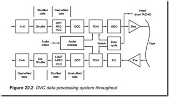
The record and replay system for DV is shown in block diagram form in Figure 22.2. Following A-D conversion in the record mode, the data is ‘shuffled’ by bringing together 16 macroblock samples from widely separated picture areas and assembling them in what appears to be a random sequence to reduce statistical distortion due to compression ratio bias, and to give best-possible ‘trick’ and still-frame reproduction during playback. Later in the chain, the data is de-shuffled to regain correct order for record- ing on tape. Next comes the data-compression stage, and then ECC, a form of Reed–Solomon protection, primarily to combat the effects of tape mis- tracking and dropout. The video data is then multiplexed with audio data and other control and housekeeping data by the time-division multiplex (TDM) switch. The video data only occupies about one-half of the dura- tion of a head scan. The remainder is used for the audio and control/ housekeeping data streams. Finally, the data is modulated and fed via a drive amplifier to the recording heads.

