The video track
Figure 21.19 shows four adjacent tracks on the tape. Track 1 is laid down by head A, and the ‘phasing’ of the spinning video head drum is arranged so that the A head enters on to the tape and starts to record just before a field sync pulse arrives. It will write about seven lines of picture before recording the field sync pulse, and then go on to write the rest of the lines in the field. By the time line 306 has been recorded, head A is leaving the top of the tape, having recorded one field of 312½ lines; head B has entered onto the tape and is about to record track 2, consisting of the next sync pulse and field; and the head drum has turned through half a revo- lution, or 180°. During this time, the capstan has pulled the tape through
the machine just far enough to ensure that track 2 lays alongside, and just touching, track 1. Track 3 is laid down by head A again, track 4 by head B and so on.
We can see, then, that signals recorded towards the lower edge of the tape correspond to those in the top half of the picture and vice versa. Thus, a tape damaged by creasing along the top edge may be expected to give a horizontal band of disturbance in the bottom half of the reproduced pic- ture. Around the period of the head changeover point, both heads are at work for a brief instant, one just about to run off the top of the tape, and the other having just entered at the bottom. Thus, there is an overlap of information. All VCRs incorporate a head switch which electronically switches between the heads at the appropriate time, just before the field sync pulse. As should now be clear, this takes place at the very bottom of the picture, and any picture disturbance due to head changeover during record and replay is hidden by the slight vertical over-scanning which takes place in a correctly adjusted TV.
Miniature VHS head drum
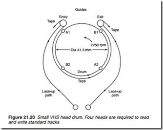
The 62.5 mm drum diameter of the standard VHS specification is a great handicap in portable video equipment. To achieve a deck size small enough to be accommodated in a light camcorder, a small head drum is used: it is 41.3 mm in diameter. To permit record and playback of standard VHS tracks, some complexity in the mechanics and electronics of the machine is unavoidable, and Figure 21.20 shows the essence of the arrangement. The travel of the tape guides follows a longer and more sin- uous path than before, to wrap the tape around 270° of the periphery of
the small drum, which rotates at 2250 rpm. This high speed is calculated to sweep a single drum-mounted head along the entire length of a stan- dard VHS video track during its contact with the wrapped tape. The inclined and continuous ruler-edge around the lower drum assembly maintains the tape at the normal 5.302° angle to the head-sweep path.
Plainly, one pair of heads will not suffice to work this system. At the point when one head is leaving the tape wrap, there needs to be another just 90° ahead, the point where it is just entering the tape wrap. This ensures continuity of signal feed onto the tape, whose linear speed around the drum conforms to standard VHS specifications—2.34 cm/s for SP mode, 1.17 cm/s for LP mode. If the head which has just left the tape is writing or reading ‘A’ tracks, the one ahead of it and one behind it must be ‘B’ heads with azimuth angles cut accordingly. Hence, the A-B-A-B con- figuration of the four heads around the drum is shown in Figure 21.20. Each head scans every fourth track on the format-standard tape.
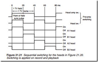
At any given moment only one of the four heads will be active in record or playback, and since two others will be in contact with the tape at this time a four-phase head-switching system is required during both record and replay. Figure 21.21 shows the switching sequence and the time rela- tionship of the video signal to the active period of each head. The switch- ing system is the same in record and playback modes, though of course the routing of the video FM carrier is opposite.
It can be seen, then, that four heads are necessary in a ‘small’ VHS head drum to do the work of the two in a conventional drum. If separate heads are provided for SP and LP eight heads are required on the drum, though they can be mounted in four chips, each carrying two windings and two head gaps. Some VHS camcorders are additionally fitted with a flying erase head, giving an effective total of nine heads around the drum periphery, with a multi-winding rotary transformer to couple the record- ing signals to the heads.
Video-8 format was designed from the outset for a two-head 40 mm- diameter drum in a small camcorder. Even so, further miniaturisation has led to the use in Video-8 and Hi-8 camcorders of the same small-head tech- nique, with a drum of 26.6 mm diameter.


