The network
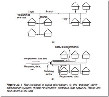
There are two basic methods of cable distribution. The more traditional is the tree-and-branch system (see Figure 23.1a) in which all available programmes are continuously sent over the network in separate channels,
with user selection by means of some form of switch at the receiving point. This was the modus operandi of the original radio and TV cable system, in which each household may be regarded as being on the end of a ‘twig’.
The alternative and better system is termed a ‘switched-star network’, shown in Figure 23.1b. Here the available programmes are piped to a ‘com- munity-central’ point analogous to a telephone exchange. The subscriber can communicate with the ‘exchange’ and request the desired pro- gramme(s) to be switched to his line for viewing, listening or recording. The advantage of the switched-star network is its interactive capability, whereby the subscriber can ‘talk-back’ to a local or central exchange; this opens the possibility of the ‘single-fibre’ household in which all communications serv- ices (radio, TV, telephone, internet, banking, public-utility meter reading, text and data, etc.) come into the dwelling via a single link which can, by means of recording devices at either end, be utilised during off-peak and night hours. The switched-star configuration lends itself well to Pay-TV (either pay-by-channel or pay-by-programme) because security is more eas- ily arranged. It is simpler to deny a programme to a non-subscriber by a cen- tral ‘turn-key’ process than by expensive signal scrambling and ‘authorised unscrambling’ systems of the sort described in the previous chapter.
Propagation modes in glass-fibre cables
Since the basic transmission ‘vehicle’ in fibre-glass cables is light energy we must now see how the signal is launched into the cable and intercepted at the receiving end. Depending on the distance to be covered, the send- ing device may be an LED or low-power semiconductor laser operating on a wavelength (infra-red) around 850 nm. The radiant energy in the send- ing device is surprisingly small, typically 200–300 1W for an LED and 1–3 mW for a laser. The fibre termination is an integral part of the light- source encapsulation for maximum coupling efficiency, permitting virtu- ally all the light to be concentrated in the cable.
The receiving device is a light-sensitive diode, again intimately coupled to the fibre end. For low noise and highest possible sensitivity this pick-up device is ‘tuned’ to the light wavelength in much the same way as a radio set is tuned to an RF transmission. For short-haul reception a silicon PIN photodiode is generally used; with long-distance fibre cables greater sensi- tivity can be obtained by using an avalanche photodiode which combines the property of light detection with an internal amplification process. A PIN diode (p-type, intrinsic, n-type diode) with a near perfect resistance at RF and microwave frequencies that depends on the DC current through it.
The glass-fibre core, made of silicon dioxide (SiO2) glass, is of very small diameter, typically 50–100 1m, surrounded by an intimately bonded cladding layer of about 20 1m thickness. Further layers give strength and environmental protection, the outer jacket consisting of a tough waterproof polyurethane cover. The transmission of light along a glass fibre depends on the phenomenon of total internal reflection in which the light, when it
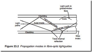
encounters the inner surface of the fibre wall, is ‘bounced’ by the mirror-like wall surface back into the fibre. Light can enter the fibre end at any angle and the bounce path in transmission can thus take several forms, as shown in Figure 23.2. Large bounce angles give rise to a long path length (in terms of the passage along the entire cable) and are called high-order transmission modes; at lesser angles the total path length is shorter, described as low- order transmission mode. A beam which travels down the axis of the fibre takes the shortest possible path length in what is known as axial mode.
The nature of light propagation down a fibre depends on its diameter and on the difference in refractive index between the fibre core and its cladding material. Where a sudden change of refractive index is present at the fibre wall we have a step-index fibre in which several modes (high- and low-order) are taken by the light. An alternative form of construction is the graded-index fibre, where the interface between ‘core’ and ‘cladding’ rep- resents a more gradual change in refractive index. This has the effect of making the light rays turn less sharply when they encounter the fibre wall and thus reduces reflection loss, as shown at the top right of Figure 23.2. Low-order modes predominate in such a graded-index fibre cable, and such high-order modes as are present travel faster along their longer path, reducing the fibre-dispersion effect described earlier. Graded-index fibres offer a low transmission loss and greater bandwidth than step-index types, at the expense of higher production costs and greater coupling losses at the junctions between the fibre and the sending and receiving devices.
Both step- and graded-index fibres operate in what may be called mult- imode with many possible light path angles within the fibre. If we can arrange a fibre to concentrate on the axial mode we shall significantly reduce the transmission loss. In this monomode system a high-grade glass core is used, with a small diameter in the region of 5 1m (about one-tenth of diameter of multi-mode cable cores). The light wavelength used here is longer, around 1.35 1m, and the much straighter light path gives very good transmission efficiency. Repeaters (regenerators) are therefore required at much longer intervals than in conventional fibre (and particularly co-axial) systems, and in a typical monomode transmission system repeaters can be as much as 30 km apart; this economy in equipment easily outweighs the cost disadvantage of the monomode fibre cable itself.
For repeaters generally, the operating power can be sent down the cable in co-axial systems, as described earlier for domestic masthead amplifiers. Fibreoptic cable plainly cannot carry DC, but conductive members can if required be incorporated in its protective sheath, or local power sources can be used, in view of the long intervals between repeaters made possi- ble by fibre-optic technology. Many thousands of kilometres of fibre-optic cable are in use in the UK, primarily by British Telecom.

