Video graphic array
The video graphic array (VGA) interface was introduced in 1987 and since then it has become the standard connection between a PC and a display unit. The layout of the 15 pins and their functions is displayed in Figure 25.6. The original VGA connector was designed for a resolution of 640 X 350 with 8-bit colour coding giving 256 different colours. Pins 4, 11, 12 and 15 formed a unidirectional or a bidirectional communication medium. One of their functions is to identify the type of display and its capabilities. Pin 15 may also be used to turn the display on and off. The VGA connec- tor was retained in its 15-pin format by later improved adaptors such as the super VGA (SVGA) and extended VGA (XVGA) designs. These added new features to the systems and also added support for higher resolutions such as SVGA at 800 X 600, XGA at 1024 X 768, super XGA (SXGA) at 1280 X 1024 and the ultra XGA (UXGA) at 1600 X 1200.
Universal serial bus
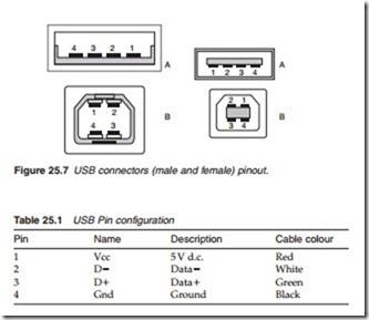
The universal serial bus (USB; pinout Figure 25.7) was first introduced in 1995 as a general-purpose low-cost connection between a PC and other peripheral devices such as a printer. Today, it is used in various devices including camcorders and projection systems. The original USB 1.0 had two levels of performance: 1.5 and 12 Mbps. It has four wires: 5 V supply with its ground and a bidirectional differential pair for data transmission (Table 25.1). The data transmission format is specified such that the serial bitstream is self-locking in that the timing information is derived from the data itself. A single USB host controller can support up to 127 peripheral
devices. Typically, though, a USB will have some half-dozen devices on its interface at any one time. The serial link performance was greatly improved with USB 2.0 which can support a bit rate up to 480 Mbps more than ade- quate to support compressed HDTV.
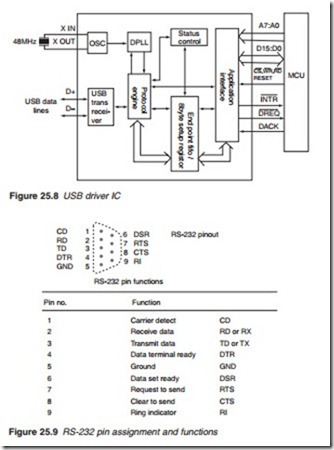
USB was designed from the start to permit what is known as ‘isochro- nous’ data, such as video and audio data in which the timing of each data packet within the overall stream must be maintained for proper recovery at the receiving end. A block diagram of a USB driver IC is shown in Figure 25.8.
RS-232 connector
RS-232 (RS stands for recommended standard) is a common serial com- munication standard for PC and peripheral devices. It has been intro- duced in consumer electronics mainly for the purposes of connecting the device to a PC for the purposes of testing and upgrading the program of imbedded flash chips. The connector may be 25-way or more usually a 9-way D-type male. The pin format and pin functions are shown in Figure 25.9. Note that an RS-232 cable must have its pins 2 and 3 switched.
Other names for the Firewire link system are IEE1394 and i-Link: they all amount to the same thing in practice, but different equipment manufac- tures prefer different names! Firewire is a very fast (up to 400 Mbps) serial data link originated by Apple Computers as a LAN (local area network)
protocol for computers, and now adopted as a standard interface for domestic digital exchange between boxes: it can carry entertainment, com- munication and computing data.
The Firewire data is carried by a cable having two individually screened twisted-pair cables, one for NRZ (non-return-to-zero) data and one for strobe pulses as shown in Figure 25.10. Exclusive-OR gating of the two pulse trains provides the system clocking pulses. The pulse amplitude of each train is 220 mV, centred on a bias voltage of 1.86 V. The data stream has two components: a relatively slow asynchronous unidirectional pulse train for control purposes; and, time-interleaved with it, a very fast isochronous one which carries ‘payload’ data in the form of variable-length packets, with header, ident, address, data and error-check components. A negotia- tion and arbitration process is used for access control in a Firewire network.
The Firewire link system is bidirectional, with a capability of 63 devices on a single bus, and a vast number of them on a bridge-bus system. Firewire ports are provided on some computers, on DV-interface com- puter cards, digital TVs and STBs as well as DV and D-VHS cassette decks and camcorders.


